Section C4 Stormwater
Stormwater is a general term for rainfall after it has fallen and runs off surfaces (such as roofs, pavements, carparks, roads, gardens, vegetated open space and the like). It includes water in stormwater pipes and channels and is a significant proportion of the natural water cycle.
All development has an impact on stormwater behaviour from increasing impervious surfaces, changes to water flow through diversions and drainage, and through potential impacts on water quality. The increase in impervious surfaces across the city reduces soil moisture with rainwater unable to reach and permeate our soil. While traditional engineering solutions for water capture and discharge are efficient, nature-based solutions can provide better outcomes for the overall environment.
Nature-based solutions aim to capture and retain stormwater in the soil, increasing water availability for tree roots, allowing water to filter naturally into the soil. This increases resilience, reduces runoff and flood risk, and supports biodiversity and environmental health during periods of low rainfall. A higher moisture level in the soil supports trees to transpire at maximum efficiency. This cools the environment and in an urban context, helps combat the urban heat island effect.
A range of measures are required to effectively manage stormwater runoff; to recharge groundwater; to increase permeability of our urban soil structure to recharge groundwater; to control the amount of stormwater flowing into waterways; and to improve water quality.
The consideration and management of the water cycle impacts design and outcomes of individual and surrounding development. Sustainable stormwater management requires the application of controls on stormwater to mitigate, manage and control changes to the natural water cycle, to protect environmental values and to protect human life and assets. Integrating natural based solutions like bioretention basins, green roofs, vegetation retention, permeable paving and other green infrastructure with a development proposal can assist stormwater management.
This section contains provisions for development applications (DA) relating to water flows, runoff, conservation, detention, drainage, groundwater and water sensitive urban design. Development controls are to be met to ensure a balance of the competing needs of development and the environment, and water use is sustainable.
This Section applies to all development.
The following sections may also apply to development:
Associated technical manuals
- Stormwater and Water Efficiency for Development Technical Manual, City of Newcastle (CN)
- Standard Drawings, CN
Significant references for additional information
- AS/NZS 3500 Plumbing and Drainage (as amended)
- Australian Rainfall and Runoff, 2019 (as amended)
- Australian Runoff Quality: A Guide to Water Sensitive Urban Design, 2006, Engineers Australia (as amended)
- NSW MUSIC Modelling Guidelines (BMT WBM, 2015)
- Newcastle MUSIC-link (Model for Urban Stormwater Improvement Conceptualisation)
- Managing Urban Stormwater: Soils and Construction Volume 1, 4th Edition March 2004, Landcom
- Water Sensitive Urban Design Technical Design Guidelines for South East Queensland (South East Queensland Healthy Waterways Partnership, 2006)
- Bioretention Technical Design Guidelines (Water by Design, 2014)
- Construction and Establishment Guidelines: Swales, Bioretention Systems and Wetlands Version 1.1 (South East Queensland Healthy Waterways Partnership, 2010)
- Guidelines for riparian corridors on waterfront land, Department of Primary Industries, Office of Water
Other references for additional information
- Urban Water Cycle Policy 2017, Newcastle City Council
- Newcastle City-wide Floodplain Risk Management Study and Plan, Final Report, June 2012, Newcastle City Council
- Newcastle Stormwater Management Plan, 2004, Newcastle City Council
- Water Sensitive Urban Design Book (Landcom); Book 1: Policy and Book 2: Planning and Management
Water sensitive design solutions for catchments above wetlands, Hunter and Central Coast Regional Environmental Management Authority
- Outline CN's requirement for stormwater management for development.
- Adopt a whole of water cycle approach to development.
- Promote sustainable practices in relation to the use of water resources for human activities.
- Ensure an appropriate quality and quantity of water enters waterways.
- Protect and enhance waterways, watercourses, wetlands and their riparian corridors.
- Promote soil infiltration and ensure stormwater is controlled and managed appropriately.
- Promote best practice and innovative water sensitive urban design solutions.
A word or expression has the same meaning as it has in Newcastle Local Environmental Plan 2012 (LEP 2012), unless otherwise defined. Other words and expressions include:
- Absorption trench – is a trench excavated into the ground for the purpose of storing an initial volume of rainfall before that water seeps into the soil in which the trench is excavated.
- Annual exceedance probability (AEP) – is the probability that a flood of a given or larger magnitude will occur within a period of one year. Its reciprocal is equivalent to average recurrence interval (ARI).
- Bioretention rain garden (or biobasin) – is a vegetated bed of filter media for the purpose of capturing stormwater runoff for water quality treatment through the filtration of sediment and biological uptake of nutrients.
- Bioretention swales (or bioswales) – are deliberately formed surface depressions for the conveyance of stormwater runoff that include a vegetated infiltration trench within the channel invert for the purpose of water quality treatment through the filtration of sediment and biological uptake of nutrients.
- Broad scale development – is all development other than dual occupancy and single dwelling houses.
- Coastal wetland – is a wetland identified in the State Environmental Planning Policy (Resilience and Hazards) 2021 (Resilience and Hazards SEPP), previously known as State Environmental Planning Policy (Coastal Management) 2018 (Coastal Management SEPP).
- Controlled activities – has the same meaning as the NRAR Guidelines (Guidelines for controlled activities on waterfront land, Riparian Corridors, Natural Resources Access Regulator (NRAR), NSW Department of Industry, 2018)
- Discharge control – is a device that stores water and limits the rate of discharge from the development site.
- Dispersion trench – is a 600mm x 600mm trench, 1m long for every 25m² of catchment draining to it (regardless of whether or not a discharge control is used) excavated into the ground for the purpose of dispersing overflows and discharges from stormwater systems. Dispersion trenches are only for single dwellings that drain to the rear.
- Drainage – means any activity that intentionally alters the hydrological regime of any locality by facilitating the removal of surface or ground water. It may include the construction, deepening, extending, opening, installation or laying of any canal, drain or pipe, either on the land or in such a manner as to encourage drainage of adjoining land.
- Easement – is a legal right held by an owner of land or public authority in respect of another land parcel. Easements are commonly created to enable access across other properties, such as for drainage, pipelines, footways, etc.
- Erosion and Sediment Control Plan – is a plan that illustrates how erosion and sediment control will be managed during the construction phase of a development.
- Exceedances per year (EY) – is a term used for events more frequent than 50% AEP. For example, 2 EY is equivalent to a design event with a 6 month recurrence interval when there is no seasonality in flood occurrence.
- Gravel filled absorption trench – is an absorption trench filled with gravel so as to achieve a minimum 30% void ratio and allowing the surface of the trench to be treated and used similarly to the surrounding surface.
- Impervious area – is an area of impermeable surface (excluding pools and porous paving).
- Impermeable surface – is a surface that does not allow rainwater to infiltrate to the soil, such as buildings (roofs), roads, parking areas and courtyards.
- Infiltration – is the practice of discharging stormwater or drainage water to the ground.
- Infiltration trench – is a trench excavated into the soil for the purpose of dispersing all stormwater up to the 5% AEP event. Infiltration trenches will vary in volume depending on the permeability of the parent soil and should be designed by a qualified Civil Engineer based on soil permeability testing.
- Large scale development – are development sites that are larger than 5,000m².
- Major drainage system – is the part of a drainage system that carries relatively large flows. It consists of the system of streams, floodways, stormwater channels, retarding basins and street pavements. It is generally designed to protect people and indoor property from the effects of a flood with an AEP of 1%.
- Minor drainage system – is the part of a drainage system that carries relatively minor flows. It consists of the system of kerbs, gutters, roadside channels, swales, sumps and underground pipes. It is generally designed to control flows which occur frequently, typically with an AEP of 10%.
- On-site stormwater detention (OSD) – means a stormwater management practice that limits the rate of discharge from a site using outlet restriction devices. Stormwater flows in excess of the capacity of the outflow control device is temporarily stored either in tanks or surface depressions until the storm event recedes. Stormwater flows are therefore released at a controlled rate into the public drainage system.
- On-site stormwater retention – are stormwater management practices where on-site stormwater runoff is actually captured and retained within the site for re-use or infiltration and is not released to the downstream drainage system.
- Overland flow paths – are low lying areas of the local topography along which surface flows are conveyed. This includes natural overland flow paths.
- Permeable surface – is a surface treatment that allows rain water to infiltrate to the soil, such as grass, landscaping, gravel, porus pavement and coarse sand.
- Permissible site discharge (PSD) – is the maximum rate at which stormwater is permitted to be discharged from a given site area.
- Porous paving – is paving that maintains a high degree of permeability to allow rainfall to infiltrate the substrate and not produce runoff in common rainfall events.
- Public drainage system – is a drainage system owned and operated by CN or the Hunter Water Corporation.
- Riparian Corridor – is a transition zone between the land, also known as the terrestrial environment, and the river or watercourse. It has the same meaning that is used in the Controlled activities – Guidelines for riparian corridors on waterfront land (NSW Department of Planning and Environment, undated).
- Riparian Zone – is a transition zone between land and a waterway (creek, watercourse, wetland, estuary or river). They provide ecosystem corridor services and support waterway stability. They help buffer land from erosion impacts during extreme storms. Generally, a width of 40m is the minimum viable riparian zone. Under the Water Management Act 2000 and guidelines, riparian zones include both the waterway 'floor' and land beyond the top of the waterway bank (Controlled activities – Guidelines for riparian corridors on waterfront land, NSW Department of Planning and Environment, undated). The top of bank is measured by Digital Terrain Model, site engineering survey or similar. See also Vegetated Riparian Zone.
- Runoff – is the portion of rainfall that flows across the ground surface as water.
- Site drainage line – is a piped drain that conveys stormwater from a development site to the public drainage system.
- Single dwelling – a single dwelling shares the same definition as 'dwelling house' defined in LEP 2012.
- Small scale development – are development on sites that are smaller than 5,000m2.
- Soil and water management plan – means a plan that illustrates how stormwater, runoff and soils will be managed on the site. The plan should demonstrate the feasibility of both the proposed stormwater management system, including water quality, conveyance and discharge controls. The plan should also demonstrate any proposed pre, during and post construction phase measures for the management of all site water including ground and surface waters. This will include proposed erosion, sediment and water quality control measures and dewatering controls as required. The plan should be supported by preliminary hydrological calculations and other information in the accompanying Statement of Environmental Effects.
- Stable point – is a location, downstream of a point discharge or within a waterway, where scour treatment is not required to manage ongoing erosion risk. For example, at the bank toe of a receiving waterway, or a point where longitudinal grade reduces to less than 3 percent, or a location where flow depth and velocity do not impact the durability of land or assets.
- Stormwater – is the runoff from rainfall events.
- Stormwater channel – is a constructed channel with well-defined bed and banks, used to convey stormwater or floodwater.
- Stormwater discharge – is the disposal of flows from the site that occur when the capacity of the site stormwater controls is reached and such overflow.
- Stormwater harvesting – is the collection, storage and use of stormwater for domestic, industrial, irrigation or other purposes.
- Stormwater management plan – is a plan that details the proposed use of structural infrastructure and treatment techniques to both improve stormwater quality and mitigate excessive flows and may include dewatering controls as required.
- Stormwater surface flowpath – is land that carries concentrated surface flow during a rainfall event, the width, shape and gradient of which is designed to cater for the flow produced by a 1% AEP rainfall event. Includes a flowpath from the spillway of an on-site detention system.
- Swale – is a deliberately formed surface depression for the storage or conveyance of stormwater runoff. Swales can be lined with rock, turf or other vegetation.
- Vegetated Riparian Zone – is the inner portion of the riparian zone: closest to the top of a waterway bank. The top of bank is identified using Digital Terrain Model, site engineering survey or similar. See also Riparian Zone (Controlled activities – Guidelines for riparian corridors on waterfront land, NSW Department of Planning and Environment, undated).
- Water cycle management plan – is a plan that identifies additional opportunities to minimise reticulated mains water use. The plan should detail the whole of the water cycle and any public health issues. It may also include consideration of the storage and use of grey water and the installation of water efficient appliances.
- Water sensitive urban design – means planning and design of the urban and built form with the incorporation of the total water cycle and recognition of conservation principles and reuse.
- Waterfront land – has the same meaning as in the Water Management Act 2000.
Objectives
- Ensure appropriate plans and documents are provided to adequately assess stormwater management, having regards to the scale and potential impacts of the proposed development.
Development category | Application requirements | Explanatory notes |
Type 1 Development proposals that are a scale of dual occupancy or smaller | Submit a Stormwater Management Plan applying Onsite Controls. The technical manual includes several Deemed to Comply controls. | With reference to site controls in CN's Stormwater and Water Efficiency for Development Technical Manual, Type 1 and 2 developments are considered 'small scale', while Type 3 developments are 'large scale'. In circumstances where Type 1 and 2 development sites are heavily constrained and deemed to comply controls cannot be implemented, additional input from specialists or modelling may be required to demonstrate that the objectives and controls have been satisfied. Erosion and sediment control plans are to be included for all three development types. Refer to Section C5 Soil Management for further information about the requirements for erosion and sediment control plans. |
Type 2 Development proposals with:
| ||
Type 3 Development proposals with one of the following:
| Submit a Water Cycle Management Plan including hydrological and hydraulic modelling to demonstrate compliance with development controls and Stormwater and Water Efficiency for Development Technical Manual. MUSIC modelling shall be in accordance with Newcastle MUSIC-link. | |
Development on sites which contain or are adjacent to waterways and riparian zones. | Designs clearly indicate:
|
|
Development proposing waterway crossings and adjustments where deemed necessary. | Designs for proposed waterway crossings and adjustments are to include:
| Designs are to be prepared by a suitably qualified engineer and may require input from a suitably qualified geomorphologist. Links to guidelines and checklists for vegetation management plans are available in the Urban Forest Technical Manual (Appendices). |
Plan requirements – all development types | ||
The stormwater management plan or water cycle management plan (whichever is submitted with the DA) includes the following items:
| ||
Coastal wetland catchment | ||
A large portion of the LGA is in the upstream catchment of coastal wetlands, protected under the Resilience and Hazards SEPP. As development upstream of a coastal wetland can affect the health of the wetland environment, development controls have been created to manage runoff from development in this catchment. If the site is in the Coastal Wetland catchment area (Map C4.01) the Stormwater Management Plan or Water Cycle Management Plan must meet the relevant hydrology objectives. | ||
Objectives
- Ensure stormwater is mitigated and controlled to minimise nuisance, including to adjoining properties, and public roadways and other spaces.
Controls (C) | Explanatory notes |
C-1. Surface levels are to be graded so sites are generally free draining with sufficient overflow capacity to ensure waters do not enter buildings when underground drainage systems are beyond their capacity. | Australian Standard 3500.3 – Stormwater drainage (as amended or replaced) sets appropriate standards for stormwater collection and is to be followed during design and construction. The Stormwater and Water Efficiency for Development Technical Manual provides more guidance on stormwater collection and should also be referred to. |
C-2. Small hardstand areas are graded towards landscaping within the property boundary for infiltration into soil. | |
C-3. Install drainage pits so that nuisance water does not collect at low points. | |
C-4. Connect gutters, down pipes and pits to the stormwater management system for the site. | |
C-5. Overflows from onsite paved areas adjacent to a property boundary are to be directed by a kerb or formed gutter to drain away from neighbouring properties. | |
C-6. Manage runoff generated by more intense rainfall to not compromise downstream drainage systems beyond their design criteria. | |
C-7. Runoff from development up to and including the 5% AEP shall be collected and drained underground. Public drainage (minor system) has a design capacity of the 10% AEP and connections from private development shall be made subject to the 10% AEP hydraulic grade line of the public drainage being lower than the property drainage system. | |
C-8. Drain runoff from the development up to the 1% AEP event to the major drainage system so it poses nil adverse impact to neighbouring properties. | |
C-9. Development ensures that peak runoff from the site for all events is not greater than the natural drainage conditions of the site. | |
C-10. Development sites are to accommodate natural overland flow from adjacent properties, and where these flows continue downstream to other adjacent properties they are not to be concentrated. | |
C-11. A minimum of 90% of the impervious site area is to be connected to the onsite controls. |
Objectives
- Maximise the reusability of stormwater through appropriate storage solutions.
- Ensure that post development runoff matches the natural water runoff regime as closely as possible.
- Establish stormwater management requirements for development in coastal wetland catchments and minimise impacts of stormwater run-off on coastal wetlands.
Controls (C) | Explanatory notes | ||||||||||||
Onsite storage can reduce stormwater runoff from development sites. Detention systems shall be included to ensure peak runoff flow rates from developments do not exceed natural conditions. In addition, rainwater runoff from clean surfaces like roofs can be stored and reused onsite through non-potable water uses to reduce demand on the potable water supply. Rainwater storage requirements are based on the development types in sub-section 7.0. 'Deemed to Comply' solutions are developed for small scale development (Type 1 and 2) to simplify the rainwater storage calculation (see Table C4.01) and ensure modelling is only provided where necessary (Type 3 or other complex development). C-1. Storage requirements are outlined in Table C4.01 for development outside the coastal wetland catchment. Storage requirements for development in the coastal wetland catchment are outlined in Table C4.02.
Table C4.01: Storage required when outside Coastal Wetland Catchment *Where runoff from Type 1 developments is expected to exceed the capacity of the downstream network, additional detention storage will be required. | 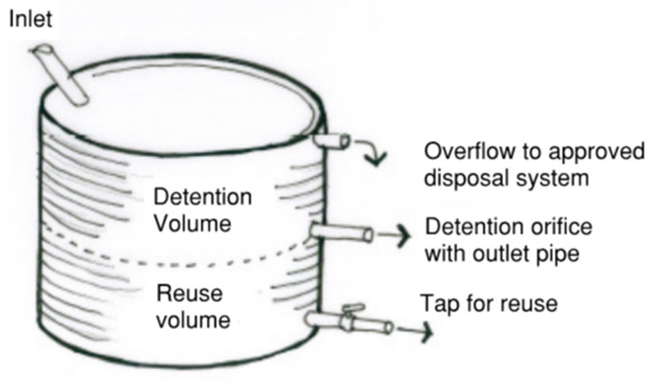 Figure C4.01: Example of above-ground tank with reuse and detention portions Figure C4.01: Example of above-ground tank with reuse and detention portionsDetention requirements for roof areas can be achieved in above-ground tanks (where possible) as shown in the sketch above. Rainwater for reuse is provided in the lower portion, while detention is provided in the upper portion. An orifice hole is cut into the tank at the bottom of the detention portion to act as a flow control. Where a charged overflow system (i.e. in rearward draining sites) for an above-ground tank cannot accommodate a separate detention orifice hole discharge, then the detention volume requirement is to be converted to reuse storage. Detention storage requirements for Type 2 developments vary with the impervious area of a site. Development sites with less than 50% impervious area shall store the equivalent of 12mm of rainfall over the impervious site area to meet detention requirements. Sites between 50% and 100% impervious area shall store the equivalent of between 12mm to 25mm of rainfall, being linearly interpolated as shown in Equation 1 and Figure C4.02. 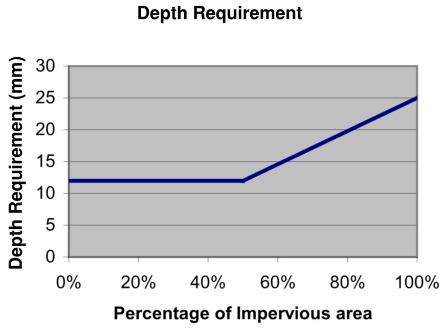 Figure C4.02: Impervious area to storage requirement relationship Figure C4.02: Impervious area to storage requirement relationshipPorous paving (example below) is not included in the impervious area calculation provided that runoff will not cause adverse impacts if paving loses porosity. 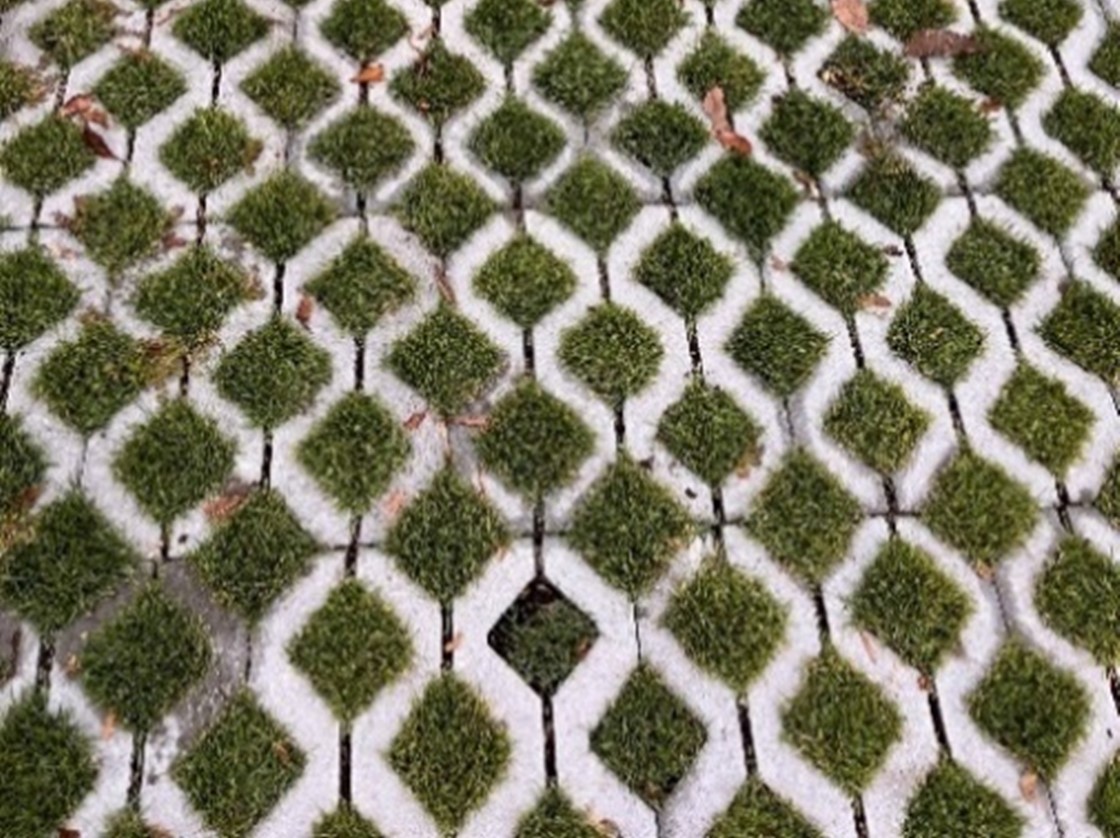 Figure C4.03: Porous Paving Example Figure C4.03: Porous Paving ExampleStrip driveways (example below) can be used within the property boundary to reduce total impervious area. 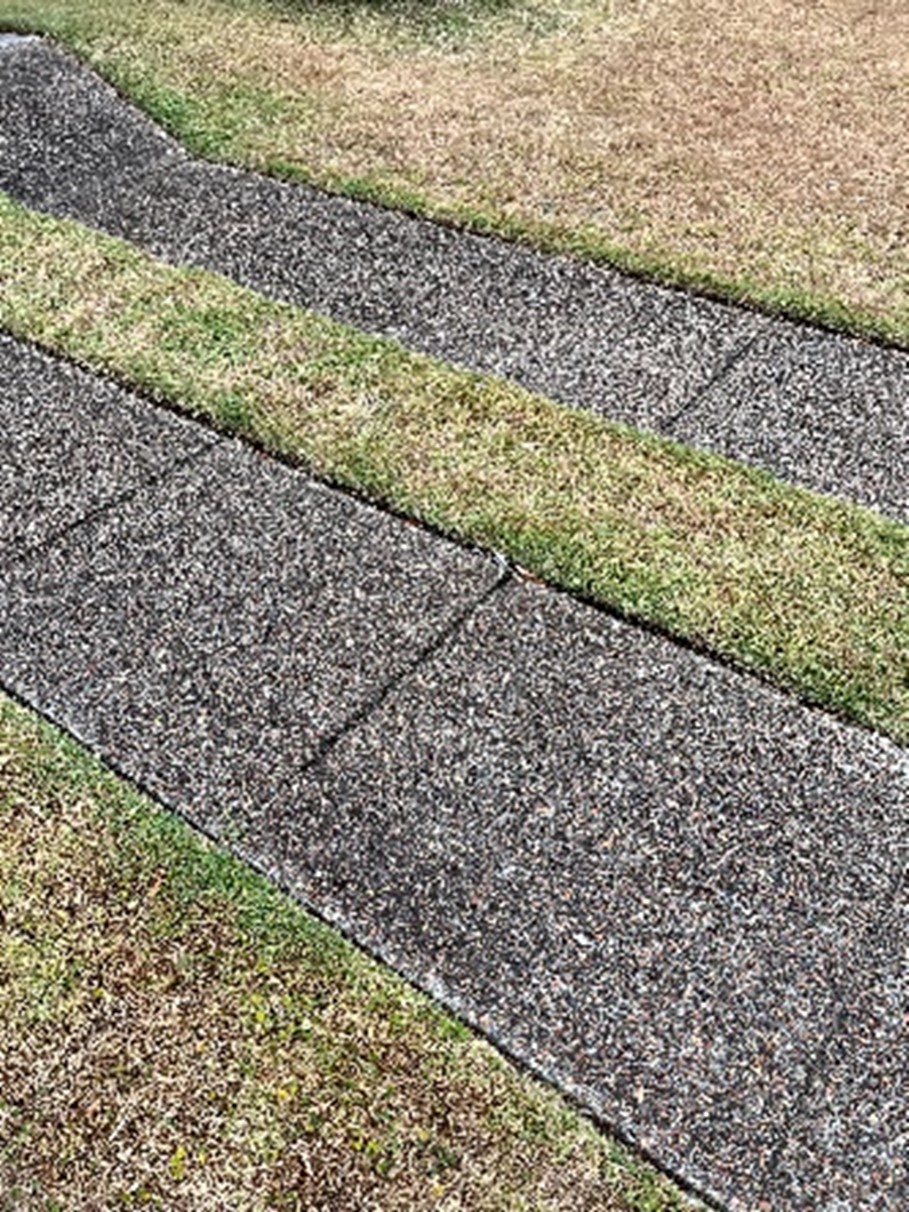 Figure C4.04: Strip Driveway Figure C4.04: Strip DrivewayWhere possible, small hardstand areas are to be graded towards landscaping. Methods to calculate Stream Erosion Index are detailed in the Stormwater and Water Efficiency for Development Technical Manual. Contact CN for a copy of mapped streams. | ||||||||||||
C-2. Equation 1 does not apply to additions to existing buildings. Where the impervious area of a development site exceeds 200m2, detention storage for additions is calculated using a simplified rate of 2m3 per 100m2 of additional impervious area. | |||||||||||||
C-3. Storage can be in a detention tank or other control, as listed in the onsite development controls. Where a detention tank is used, an orifice (or pipe) can be placed at the base of the detention portion of the tank to control flows, sized as follows:
| |||||||||||||
C-4. Alterations and additions within the existing building footprint, such as building a second floor, do not require additional onsite controls. However, in the case of a total redevelopment of that footprint, the existing footprint will not be credited, and the development must achieve the full storage requirements. | |||||||||||||
C-5. Where there is a change in the impervious area of an existing site as a result of a full redevelopment, the entire predeveloped site is to be considered in natural condition in regard to impervious areas for design purposes. | |||||||||||||
C-6. Sites with direct connection to tidal water bodies are not required to have detention provided the pipe network to the tidal water body has sufficient capacity for flows from the site and ensures erosion and scour is managed at the outlet. | |||||||||||||
C-7. The roof area directed to a rainwater tank must be maximised, to both increase the effectiveness and reliability of the reuse system and reduce the degree of stormwater treatment required for those areas not draining to the rainwater tank. | |||||||||||||
C-8. All rainwater reuse tanks must be fitted with a first flush device to prevent contaminates fouling water and to prolong the life of the tank. | |||||||||||||
C-9. For Type 3 development sites, it will be necessary to undertake a more rigorous hydrologic and hydraulic assessment to demonstrate that the flooding and runoff regimes are being satisfied in accordance with the development controls and the Stormwater and Water Efficiency for Development Technical Manual. Detention systems shall be designed to ensure post development flows do not exceed natural flows during the following events: 50% AEP, 20% AEP, 10% AEP, 5% AEP, 2% AEP, 1% AEP. | |||||||||||||
C-10. Where a large-scale storage solution, such as on-site detention is provided as part of the subdivision, individual tank storage volumes may be reduced by a commensurate amount. | |||||||||||||
C-11. Hydrology (Stream Flow) Objectives for development above CN mapped streams: The Stream Erosion Index (SEI) is to be no greater than 2, where the SEI is expressed as the ratio of ‘post development flow exceeding the stream forming flow’ to ‘pre development flow exceeding the stream forming flow’. The stream forming flow is defined as 50% of the 2-year flow rate estimated for the catchment under natural conditions. | |||||||||||||
Storage drawdown (Applies to all development) C-12. Fit all rainwater reuse tanks with a pump to draw down and reuse water. For Type 1 and 2 developments, rainwater tanks must be plumbed into the following non-potable uses with separate pipe connections to the potable water supply:
| |||||||||||||
Storage controls for development in coastal wetland catchment C-14. To meet the hydrology objectives for development in the coastal wetland catchment, 'Deemed to Comply' solutions have been developed for small scale development (Type 1 and 2) to simplify the rainwater storage calculation (see Table C4.02) and ensure modelling is only provided where necessary (Type 3 or other complex development). The tank sizes shall be adopted for all development sites that are smaller than 5,000m2 and can be used as a guide for development sites that are larger than 5,000m2. C-15. The post development 7-day flooding hydrology (high flow) is to match the pre development 7 day flooding hydrology (high flow) up to the 80th percentile. The post development 30 day drying hydrology (low flow) is to match the pre development 30 day drying hydrology (low flow) up to the 80th percentile. C-16. Development in the coastal wetland catchment is to comply with the controls in Table C4.02.
Table C4.02: Storage Requirement in Coastal Wetland Catchment Where a BASIX or NABERS reuse volume is higher than the reuse volume for development in the coastal wetland catchment, increase the total tank size to account for the full BASIX or NABERS reuse volume below the 5mm weep hole. C-17. Rainwater tanks for type 1 and 2 development are configured such that:
| Map C4.01 at the end of this section indicates the boundary of the coastal wetland catchment area. An example of a coastal wetland rainwater tank configuration is shown in Figure 4.05 below. The "leaky tank" volume includes the detention portion for the roof catchment: 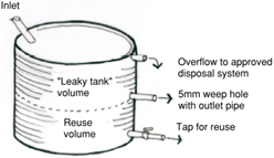 Where a charged overflow system (i.e. in rearward draining sites) for an above-ground tank cannot accommodate a separate detention orifice hole discharge, then the detention volume requirement is to be converted to reuse storage. |
Objectives
- Ensure an appropriate quality of water enters waterways.
- Minimise the potential impacts of development and associated activities on the aesthetics, recreational and ecological values of receiving waters.
- Prevent pollutants such as litter, sediment, nutrients and oils from entering waterways.
- Ensure stormwater treatment measures are designed appropriately to protect property, life and maximise infrastructure performance and useful life.
Controls (C) | Explanatory notes | ||||||||||||
C-1. All development covered by this section is to include water sensitive urban design elements to ensure the quality of stormwater runoff is managed. Depending on the type and scale of the development, different levels of treatment are required prior to discharging stormwater from a site. Table C4.03 outlines the water quality requirements with respect to development type.
Table C4.03: Water quality requirements *Additionally, Gross Pollutant Traps are required as outlined below. *Note additional hydrology targets in Table C4.04 below for development in Coastal Wetland catchment. All development is to comply, however only type 3 developments require modelling. | Onsite controls are listed in the next sub-section and detailed further in the Stormwater and Water Efficiency for Development Technical Manual. These controls can be implemented into a design to ensure water quality targets are met. Stormwater treatment measures are integrated into the urban design and landscaped areas. Passive irrigation of landscaped areas is highly encouraged to promote evapotranspiration and vegetation performance. Where possible, impervious areas (not roofs) should be graded to direct surface flows onto pervious surfaces for infiltration. | ||||||||||||
C-2. Gross pollutant traps (GPT’s) are intended to remove contaminants such as sediment, oil and other pollutants before it discharges into the receiving system. GPTs must be installed for the following developments:
C-3. Type 2 and 3 developments shall meet the targets outlined in Table C4.04.
Table C4.04: Water quality reduction targets | The reduction in pollution loads is relative to the stormwater pollution loads expected from conventional urban development without stormwater treatment measures. Contact CN 49742000 for a copy of CN mapped watercourses.
| ||||||||||||
C-4. Stormwater treatment measures are located and configured to maximise the impervious area that is treated. Devices are to be located within the property boundary. | |||||||||||||
C-5. Stormwater treatment measures must be able to bypass flows that are in excess of the design discharge in a controlled manner and are engineered to connect to suitable downstream discharge points with negligible concentrated flows resulting from overtopping or blockage of the device. |
Objectives
- Ensure onsite controls are considered and incorporated early in the development to ensure a catchment sensitive, holistic, integrated and economical design.
- Incorporate water sensitive urban design elements into the urban landscape for ecological enhancement.
- Ensure public and shared private infrastructure is delivered at an appropriate standard for easy maintenance and allowing access for maintenance to occur.
Controls (C) | Explanatory notes |
C-1. All development control requirements relating to storage and water quality can be achieved by installing onsite controls. Selection of appropriate onsite controls will largely depend on the constraints and opportunities presented by the site and are designed to integrate with the development proposal. Onsite controls may be selected from one or more of the following measures listed below depending on site constraints and the scale of development, with details contained in the Stormwater and Water Efficiency for Development Technical Manual:
| Use of onsite controls that integrate into the surrounding landscaping are encouraged, such as bio retention rain gardens by having simple "deemed to comply" controls (details in the Stormwater and Water Efficiency for Development Technical Manual). Where non-standard controls are proposed such as proprietary devices, MUSIC modelling needs to be provided to demonstrate that water quality targets are met. Where deemed necessary, the stormwater storage, infiltration or water quality system may need to be endorsed on any associated subdivision certificate for the development with a positive covenant. CN shall be nominated as the sole authority to modify, vary or release the covenant. Onsite controls are to be designed in accordance with the Stormwater and Water Efficiency for Development Technical Manual.
|
C-2. Each stormwater management system shall be indicated on site by fixing a marker plate or sign in a prominent position (other than Type 1 development). The marker plate or sign is to be provided in accordance with the Stormwater and Water Efficiency for Development Technical Manual. | |
C-3. Development that creates public assets is to comply with the development controls and be carried out in accordance with the requirements for public assets as outlined in the Stormwater and Water Efficiency for Development Technical Manual. Public Assets are to be designed in accordance with CN's Standard Drawings. | |
C-4. Provide site specific maintenance manuals for onsite controls for development sites larger than 5,000m2, or where public assets or a private shared asset is created via strata or community title subdivision. Manuals shall address maintenance issues including routine monitoring and maintenance and associated system components (such as vegetation, subsurface drainage, filter material, flush outs, etc) that could impact device performance. Carry our periodic monitoring and maintenance to ensure the system functions as designed and meets water quality and quantity targets as indicated over the device's life cycle. This includes proposed measures to protect and clean devices during the construction stage of a subdivision. All weather access tracks are to be provided to public and private assets for maintenance purposes and where fencing is installed, it shall not preclude access for maintenance. A list of maintenance manual considerations including asset handover are outlined in the Stormwater and Water Efficiency for Development Technical Manual. |
Objectives
- Ensure overflow does not adversely affect the subject site and other properties or waterways by way of intensification, concentration or inappropriate disposal across property boundaries.
Controls (C) | Explanatory notes |
C-1. After stormwater is collected and conveyed by the site's onsite controls, it must be discharged from the site via the following:
| Minimum requirements for discharge methods are outlined in the Stormwater and Water Efficiency for Development Technical Manual. CN cannot grant private drainage easements across public land. Where an easement does not exist or cannot be obtained, dwelling houses draining to the rear should have their entire roof area connecting to a rainwater tank, discharging to the street via a charged outlet where achievable. All other hardstand area are to be directed to an infiltration or dispersion trench within the property.
|
C-2. Where sites drain to the rear and it is demonstrated methods in C-1 are not possible, discharge may be by the following:
| |
C-3. Basement carparks shall be designed with a suitable drainage discharge. Where water cannot drain out via gravity, a pump-out system is to be installed and connected to the site's stormwater network, upstream of any water quality treatment devices. Basement pump-outs are not to be directly connected to the public kerb and gutter. | |
C-4. Discharge to Waterways and Open Channels - Overflow or discharge directly to waterways and open channels is generally only acceptable if it is demonstrated that no other discharge locations are possible. The number of direct point discharges to waterways should be minimised. Where stormwater is proposed to be discharged to natural waterways, designs are to clearly indicate how erosion will be avoided. Plans need to show the length and nature of scour protection extending from the end of civil drainage to a geomorphic stable point, identified by a suitably qualified person. If discharging to a natural waterway, the drainage centreline should be oriented between 45 to 60 degrees to the waterway centreline and join flows in the same direction. The outlet pipe invert must be at least 150mm above the height of standing water. | |
C-5. Where a proposed development site has frontage to a laneway and the laneway is lower than the site, the development may be drained to the surface but only if:
Where other development is proposed to drain to a laneway, the underground street drainage is to be extended into the laneway to receive the overflows in accordance with the Stormwater and Water Efficiency for Development Technical Manual. |
Objectives
- Ensure appropriate easements are provided over drainage systems on private properties.
- Ensure easements are unimpeded by development for maintenance purposes and high flow overland flow paths.
- Ensure development containing or adjacent to waterfront land maintains or rehabilitates the environmental values and drainage functions of riparian corridors.
- Ensure discharge points to waterways and/or waterway crossings do not increase the risk of erosion, blockage or flooding both onsite and offsite.
Controls (C) | Explanatory notes | |||||||||||||||||
C-1. Where the development site's drainage system serves other lands, that system is to be protected by an easement in favour of the beneficiary of the drainage system to permit the continued use of the drain. A drainage easement gives the beneficiary the right to maintain the pipes contained in the easement. Where necessary, upstream lots are to be given a legal right to drain through a development site. | The Stormwater and Water Efficiency for Development Technical Manual provides additional information on existing drainage systems and stormwater easements. Extinguishing or creating easements shall be carried out in accordance with the Conveyancing Act 1919. | |||||||||||||||||
C-2. Where an existing drainage system across the site is retained, the proposed development is not to obstruct access to the existing system. The development is to be designed to be structurally independent and not degrade the structural integrity of the drainage system. | ||||||||||||||||||
C-3. Where an existing drainage line runs under a proposed building, the drainage line and any associated easement may be diverted around the building subject to approval. Designs showing proposed alterations to the easement must demonstrate the following:
| ||||||||||||||||||
C-4. CN mapped first order streams require assessment for their riparian corridor function. Type 2 and 3 development is to be designed to protect CN mapped streams and achieve the stream erosion index (SEI) targets set in sub-section 9.0. | ||||||||||||||||||
C-5. Development discharging to waterways or is carried out on waterfront land is to meet the Water Management Act 2000 requirements and the NSW Government guidelines for riparian corridors on waterfront land. | ||||||||||||||||||
C-6. Development on sites which contain, or are adjacent to waterways, shall provide plans which meet sub-section 7.0. The provision of vegetated riparian zones and development offsets from the top of bank is preferred, in accordance with relevant guidelines and legislation, and to provide local waterway stability, drainage function, and riparian corridor values. | CN's Stormwater and Water Efficiency for Development Technical Manual, includes riparian zone definitions and offsetting guidance as set out in the NSW Government Guidelines for riparian corridors on waterfront land. | |||||||||||||||||
C-7. Where development within riparian zones, including waterway crossings are deemed necessary the following must be complied with:
|
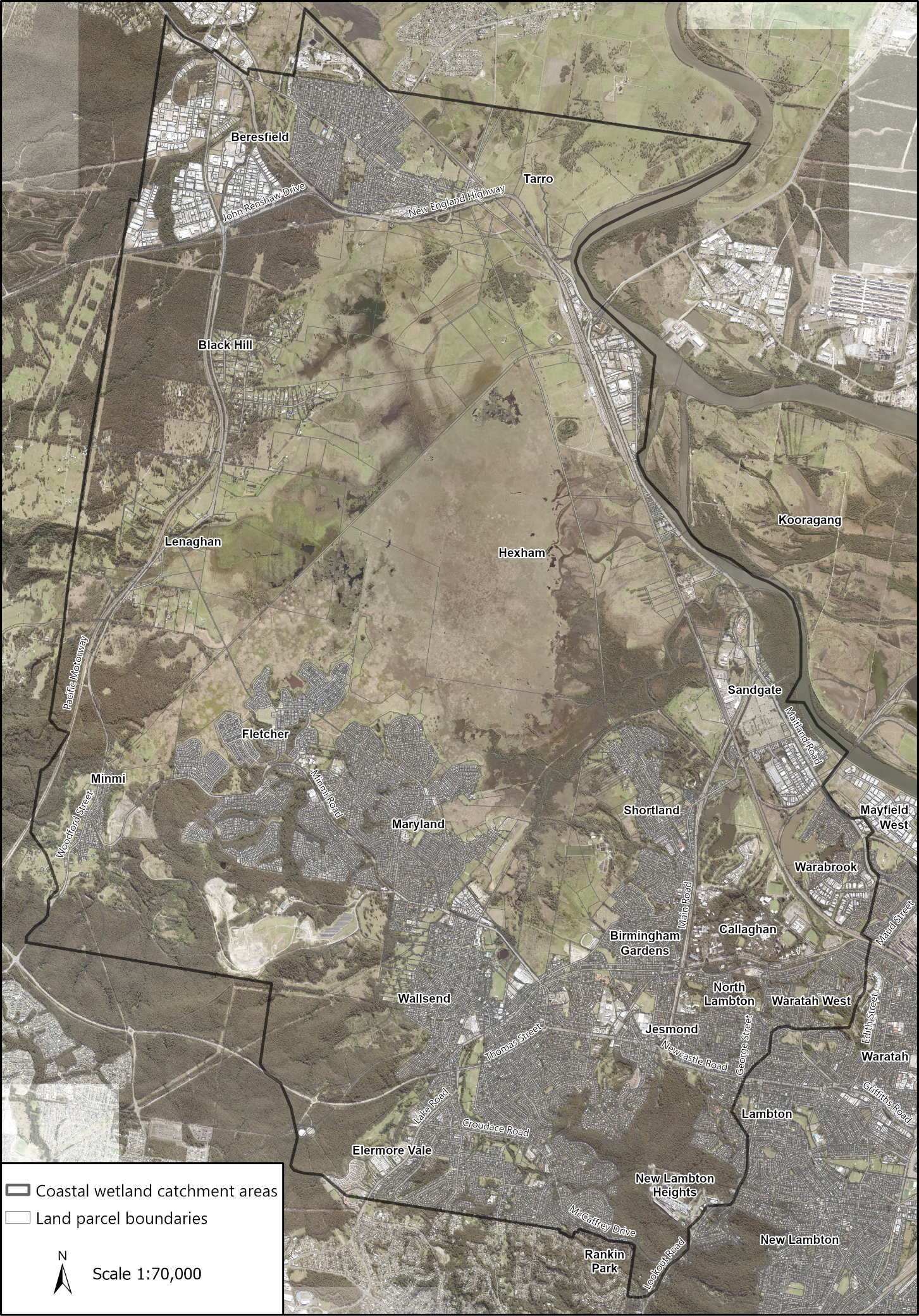 Map C4.01: Coastal wetland catchment areas