Section E8 Renewal corridors
This section applies to all development consisting of:
- new buildings or structures
- additions or alterations to existing buildings or structures.
- Newcastle Local Environmental Plan 2012 (LEP 2012)
- State Environmental Planning Policy No 65—Design Quality of Residential Flat Development
In the event of any inconsistency between this section and the above listed environmental planning instruments, the environmental planning instrument will prevail to the extent of the inconsistency.
Note 1: Additional environmental planning instruments may also apply in addition to those listed above. Note 2: The Environmental Planning and Assessment Act 1979 enables an environmental planning instrument to exclude or modify the application in whole or part. |
The following section will also apply to development:
- Any applicable land use specific provision under Part D Development controls by land use.
| Note: Any inconsistency between the locality specific provision and a land use specific provision, the locality specific provision will prevail to the extent of the inconsistency. |
- B6 Urban heat
- C1 Traffic, parking and access
- C4 Stormwater
- C6 Waste management
- C7 Safety & security
- C12 Open space and landscaping.
The following sections may also apply to development:
- B1(a) Flood management - pre 2019 flood studies
- B1(b) Flood management - post 2019 flood studies
- B2 Bush fire protection
- B3 Mine subsidence
- B4 Aboriginal cultural heritage
- B5 Historical archaeology
- B7 Land contamination
- C1 Traffic, parking and access
- C2 Movement networks
- C3 Vegetation preservation and care
- C4 Stormwater
- C5 Soil management
- C6 Waste management
- C7 Safety & security
- C8 Social impact
- C9 Advertising and signage
- C10 Street awnings and balconies
- C11 Development adjoining laneways
- C13 Liveable housing
- D1 Subdivision and lot consolidation
- E1 Built and landscape heritage
- E2 Heritage conservation areas.
Any development application (DA) lodged but not determined prior to this section coming into effect will be determined taking into consideration the provisions of the plan that applied at the date of lodgement of the application.
The Urban Design Review Panel (UDRP) provides independent, expert advice to City of Newcastle (CN) and applicants about the quality of the urban design and amenity of developments.
Some types of development must be referred to the UDRP. These include:
- Residential flat buildings
- Shop top housing
- Mixed-use development with residential accommodation component
- Strata subdivision of serviced apartments
Within the renewal corridors, other types of development may be referred to the UDRP due to their nature, location or scale, and likely impact upon the surrounding locality. These include:
- Boarding houses
- Education establishments
- Hospitals
- Multi dwelling and attached dwelling developments comprising ten or more dwellings,
- Place of public worship
- Seniors housings
- Serviced apartment
- Tourist and visitor accommodation
- Modification applications where the development consent to be modified was subject to UDRP advice and the modifications are not minor
- Any other development referred at the discretion of the Manager
The UDRP is an advisory panel only and the advice provided by the panel is to inform the assessment process. It is not the purpose of the UDRP to have any role in the determination of DAs, nor are its recommendations binding on CN’s determination of an application.
This section provides development objectives and controls for infill and urban renewal development in the five renewal corridors.
The LEP 2012 is Council's principal planning document. It provides objectives, zones and development standards such as lot sizes, floor space ratios and building heights.
The existing urban renewal corridors were identified by CN within the Newcastle Urban Strategy, which underpinned the preparation of Newcastle LEP 2003.
Good design is important to achieve a scale, bulk and height appropriate to the desired character of the street and surrounding buildings. It achieves an appropriate built form that defines the public domain, provides internal amenity and considers neighbours’ amenity.
Good design also recognises that together landscape and buildings operate as an integrated and sustainable system, resulting in attractive development with good amenity. Good landscape design enhances the development’s environmental performance by retaining positive natural features which contribute to the local context, and providing deep soil zones for vegetation and urban heat/water management.
This section provides a set of overarching objectives for the corridors supported by five ‘Character typologies’, which provide development controls for all the corridors and relate to the desired future character of that area.
Each corridor contains site specific controls which are located in the corresponding corridor section. Each corridor area is assigned a character typology, which has related built form controls.

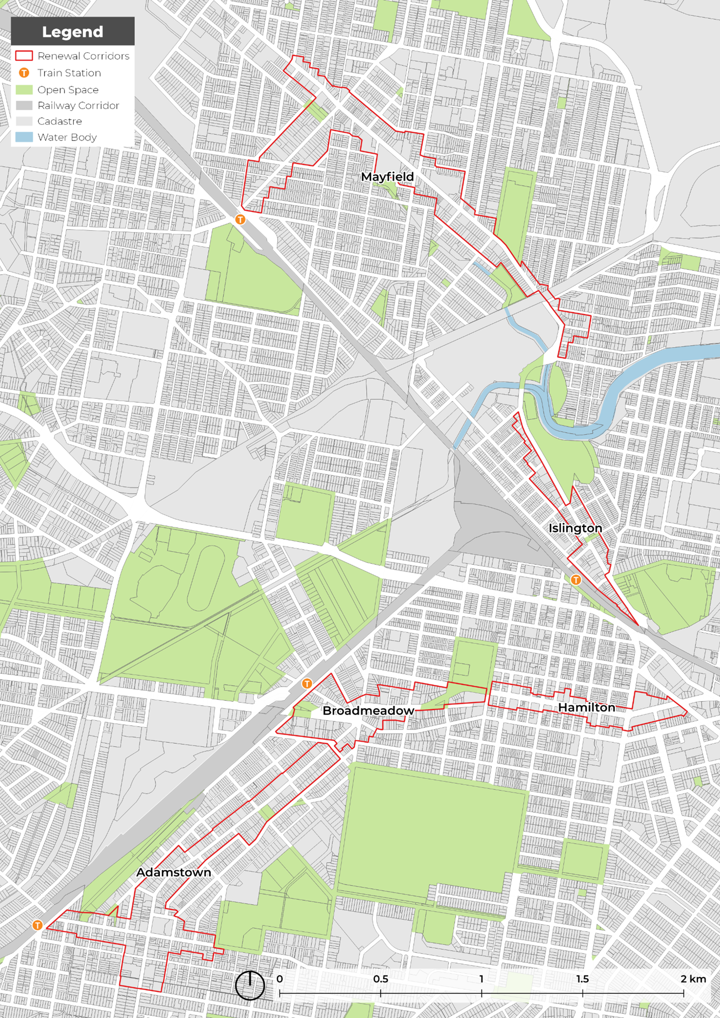
This section covers five renewal corridors identified in the map following. These corridors are:
- Adamstown (Section 1.0)
- Broadmeadow (Section 2.0)
- Hamilton (Section 3.0)
- Mayfield (Section 4.0)
- Islington (Section 5.0)
Site specific information relative to each corridor is contained in the respective sections.
An example of how to apply the controls is provided below.
Table E8.01: Example development control application | ||
Step | Description | Image |
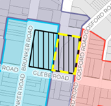
| In this example, the eastern portion of the former Adamstown Public School is identified in the purple ‘Active-Residential’ character typology. The built form controls contained in the ‘Active-Residential’ character typology apply to this site. The site also is identified as having site specific controls. |
|
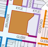
2. Identify the relevant setback for the site on the setback map. | The subject site has two ‘Active Residential’ setbacks that apply:
Refer to relevant character typology section setbacks for further detail. |
|
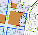
3. Identify the relevant awning and street tree requirements for the site on the awning map. | The subject site is identified as requiring an awning on the primary street. Relevant awning controls apply. New street trees are also identified. Proposals must consider how these additional plantings can be provided, and design accordingly. |
|
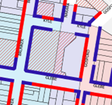
4. Identify the relevant vehicle access requirements. | The site is identified with two type of vehicle access:
|
|
5. Review site specific controls for the site. | In addition to the relevant character typology controls, this site has a range of site-specific controls outlined in Part D or the corridor section. |
|
- Ensure new development responds to the desired future character and sense of place.
- Encourage a diversity of denser urban forms and renewal of underutilised sites.
- Provide for active street frontages and lively main streets.
- Improve the public domain by providing new urban places and landscape enhancements.
- Respect heritage significance and protect quality streetscapes and contributory buildings.
- Establish a finer grain and more permeable urban fabric to improve pedestrian amenity and safety.
- Establish and reinforce gateways at key locations to improve urban legibility.
- Maximise view potential to green spaces and landmarks.
- Encourage residential intensification, mixed use developments and infill as and where appropriate.
- Encourage design quality and sustainable, green development outcomes.
- Establish appropriate transitions to adjoining lower density streetscapes.
- Ensure solar access to public spaces and footpaths.
- Ensure the bulk and scale of new development is appropriate for the site and surrounding context, and contributes positively to the desired future character and amenity of the local area.
- Ensure all people, regardless of their age, ability or mobility, have equal access to public places and buildings by providing universally accessible design and infrastructure that meets the needs of the whole community.
Development in the renewal corridors must be consistent with the above objectives.
Development Category | Application requirements | Explanatory Notes |
All applications that include the erection of a new structure or the extension of an existing structure with a height exceeding 10m are to be accompanied with a 3D model of the proposed development within the context of the Newcastle CBD 3D model. | The format should be compatible to that used by CN. Format specification requirements for the model can be provided by CN's Geospatial Information Services team. | The 3D Model should be used to illustrate the following information:
|
Any development that may require an acoustic report or a noise impact assessment. | An acoustic report or noise impact assessment is warranted when a noise-producing development is proposed near noise-sensitive areas or, conversely, when a noise-sensitive development is proposed in a noisy area. An acoustic report should:
Ensure any recommendations concerning acoustic attenuation are feasible and can be practically implemented. | Newcastle After Dark Strategy - Night-time Economy Strategy reiterates that that a developer responsible for building a residential complex needs to ‘design in’ reasonable noise mitigation (for example double glazing). Conversely, a late-night venue seeking to extend venue space or hours of live performance would need to ensure noise impacts are appropriately managed. A noise-producing development or noisy area may have a range of activities contributing to noise and is not limited to that produced from busy roads, railways, industries, live music venues, entertainment, gymnasiums, public parks and plazas in which people may congregate or host live music or events. A noise-sensitive development may include but is not limited to residential accommodation, educational establishments, early education and childcare facility, health services facility, place of public worship or the like. More guidance can be found in the Noise Guide for Local Government, 2023 (NSW Environment Protection Authority) and, Approved Methods for the Measurement and Analysis of Environmental Noise in NSW, 2022 (NSW Environment Protection Authority). |
An application for development, including a change of use involving building work. | An access report identifying the relevant matters to be addressed at the construction certificate stage, in circumstances where access constitutes a substantive public interest aspect of a proposal. Access reports should be prepared by a person who is a suitably qualified access consultant, such as a person who is appropriately accredited by the Association of Consultants in Access Australia Inc. | The Disability (Access to Premises – Buildings) Standards 2010 applies to any part of a building impacted by the application for a change of use. This section does not require anything beyond the standard, but does require information on how the standard will be met through the building design in accordance with these application requirements. There may also be other standards under the Disability Discrimination Act 1992 relevant to the public interest assessment of a proposal, such as the Disability Standards for Education 2005. |
An application for a change of use not involving building work. | An access report to consider access matters, in circumstances where access constitutes a substantive public interest aspect of the proposal. Access reports should be prepared by a suitably qualified access consultant, such as a person appropriately accredited by the Association of Consultants in Access Australia Inc. | A change of use not involving building works may generate public interest considerations relevant to the assessment of a DA, including in circumstances where it is apparent that a building may not comply with the access requirements of the Building Code of Australia. |
Land to which this section applies
This section applies to all land identified in Figure E8.01.
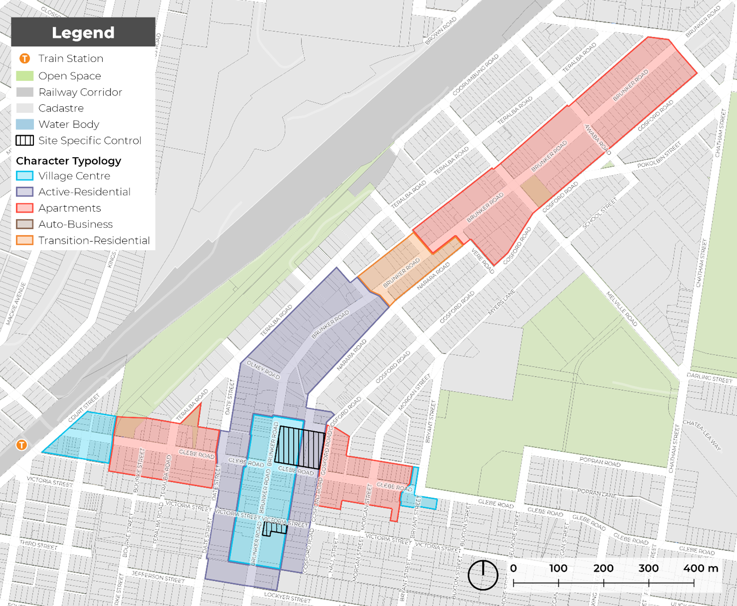 Figure E8.01: Adamstown renewal corridor area
Refer to the relevant setback and character typology for overarching development controls.
Objectives
- Reinforce and maintain a well-defined street edge along Brunker Road and Glebe Road.
- Provide space for tree planting and landscaping in desired areas.
Controls
- Front building setbacks must be consistent with those shown on Figure E8.02: and the relevant setbacks identified in sub-section 6.0 Character typologies.
- Upper level setbacks are encouraged to be used for open space and landscaping, provided privacy of adjoining uses are protected.
- An alternative building setback from the character typologies listed in this section may only be accepted where it can demonstrate in urban design terms how the design solution was developed, how it was superior, and that the alternative setback:
- is more appropriate to the specific characteristics and context of the site and its surroundings, as compared to the setback requirements that have been assigned
- will not adversely affect the amenity of surrounding properties or the wider community
- meets the overall objectives of the section in terms of built form, scale, and bulk
- is consistent with good design principles and the desired character of the area.
| Note: Any proposed alternative setback must be submitted to the council for review and approval. The proponent will be required to provide detailed design drawings, elevations, and a written justification for the alternative setback. Council will consider the proposed alternative setback against the criteria outlined in this control and may approve, approve with conditions, or reject the proposal. A pre-DA meeting with council officers is encouraged when intending to vary these controls. |
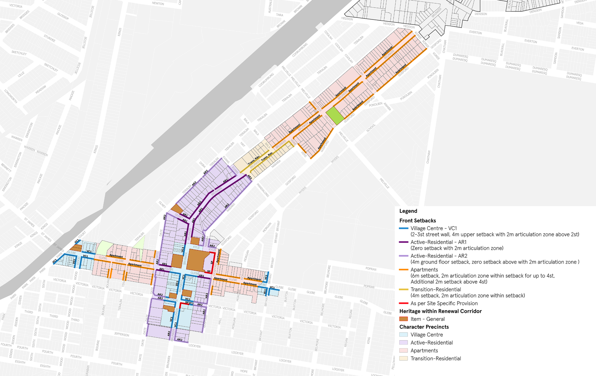
Figure E8.02: Adamstown building setbacks
Objectives
- Provide consistent awnings along active frontages.
- Increase urban tree canopy cover.
- Manage the interface between street trees and awnings.
- Ensure that awnings, street trees and street infrastructure (such as power poles, street lighting, bus stops, drainage and telecommunication pits) are coordinated in their design and that their placement does not obstruct the public domain.
Controls
These controls should be read in conjunction with Section C10 Street awnings and balconies. If there is inconsistency between controls, the controls in this section prevail.
- Awnings must be provided in accordance with Figure E8.04.
- Awnings are to be consistent with Figure E8.03.
- The underside of an awning must be no lower than 3m above the footpath.
- As shown in Figure E8.03, the depth of an awning is determined by the footpath width to allow appropriate space for planting, street furniture and lighting.
- Continuous awnings must be provided to all active frontages. Breaks in awnings may be permitted for residential lobbies for legibility and for existing street trees.
- New awnings should respond to existing awnings in terms of width, height and material. Awning material preference should complement heritage or period facades with similar materials, signage and colour treatments.
- Awnings on Primary Streets should provide a continuous awning for the entire length of the frontage. Breaks in awnings may be permitted for residential lobbies for legibility and for existing street trees
- Awnings on Secondary Streets should provide a continuation of the awning on the Primary Street, covering any active frontage for an appropriate distance relative to length of development.
- Where a proposed street tree is indicated on Figure E8.04, comprehensive redevelopment should provide new street tree planting, as per C3 Vegetation preservation and care and The Newcastle Urban Forest Technical Manual. Alternative tree locations and additional planting will be considered on merit.
| Note: The proposed tree locations are dynamic and provided as a guide. Development may consider street blister or vault planting for street trees where continuous awnings are prescribed. |
 Figure E8.03: Awnings diagram
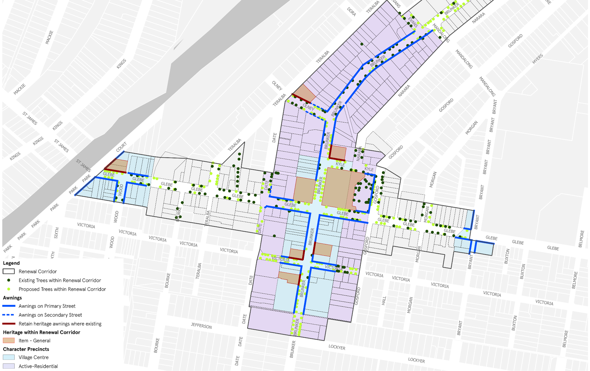
Figure E8.04: Adamstown street tree and awning map
Objectives
- Minimise access onto Brunker and Glebe Road from new development.
- Provide sufficient off-street car parking.
- Minimise impacts from car parking on the streetscape and outdoor areas on site
- Maximise opportunities for walking and cycling and where possible
Controls
- Vehicle access is not provided directly to Brunker or Glebe Road but is off side streets and rear laneways, except where no other options for access exist, as identified on Figure E8.05 Adamstown Vehicle Access.
- Existing laneways and right-of-ways are retained for access by new and existing development.
- New public laneways are provided as shown on Figure E8.05 and dedicated to Council.
- Where negotiated prior to determination of a development proposal, such laneways may be incorporated into the development or allow development of their airspace but only where this allows for unrestricted public access.
- Vehicle entrances do not dominate the streetscape and are recessed from building facades.
- At-grade (ground level) car parking is only provided where:
- it is set back behind other uses that provide activation to the street edge
- it is under cover and integrated into the built form and covered by upper levels of development or upper level open space/landscaping provision
- ceiling heights and floor levels allow for future adaption to other uses
- it is not within building setbacks
- it is not impeding an ability to meet minimum on site landscape requirements.
- Where above-ground car parking facilities are proposed they must be located to the rear of development along Brunker and Glebe Roads and appropriately screened from any street frontages by use of built form, architectural screens or landscaping.
- Driveways directly accessing Brunker or Glebe Roads, where necessary, have a maximum width of 3m per direction and contain a centre refuge where allowing two-way access. The design also minimises queuing across footpath.
- New development enhances safety and amenity of bus stops by encouraging adjoining active uses, passive surveillance, and weather protection.
- Car parking is provided in accordance with C1 Traffic, parking and access
- Development is to provide footpaths for the full width of any site frontage. Where the proposed footpath will adjoin and connect to an existing or approved footpath on an adjoining site, the width of the proposed footpath is to match this footpath width. See C2 Movement Networks for detail.
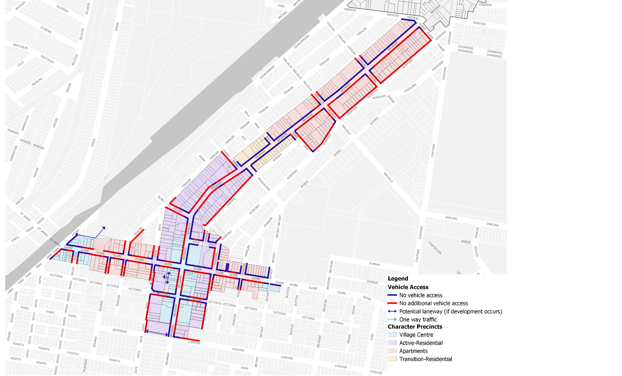
Figure E8.05: Adamstown vehicle access map
Objectives
- Guide development outcomes on specific sites.
- Ensure good design outcomes that respect local character and heritage.
Controls
Former Adamstown Public School Site
Located at 201 Brunker Road, the former Adamstown Public School is a locally listed heritage item under the LEP 2012. The site is significant due to its landmark qualities and an example of Victorian Gothic architecture that is in excellent conditions. It is complementary to the adjacent Post Office and Adamstown Uniting Church. It was constructed and opened in 1879 as the Adamstown Public School to serve the large local population following the establishment of several mines in the area. It was last used as a school in 1971 and is currently the regional office for the Department of Education, having been re-opened as the Adamstown Teacher's Centre in 1973. (Heritage NSW).
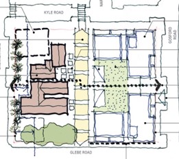
Redevelopment of the site should improve the public domain through a mixed use redevelopment. This includes improved through site linkages and a perimeter block style development with internal communal open space.
- Development of the former Adamstown Public School site should be consistent with the Figure E8.06 and Figure E8.07.
- Development of the former Adamstown Public School site at the corner setback of Brunker and Kyle Roads to incorporate an informal public open space with playground facilities.
- Through site links and pedestrian links should be provided as shown in Figure E8.06.
- On-site car parking associated with redevelopment of the former Adamstown Public School is provided at sub-grade with vehicle access from Gosford Road to maximise landscape opportunities on site, as shown in Figure E8.06.
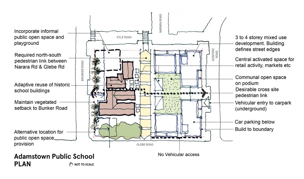 Figure E8.06: Adamstown public school plan
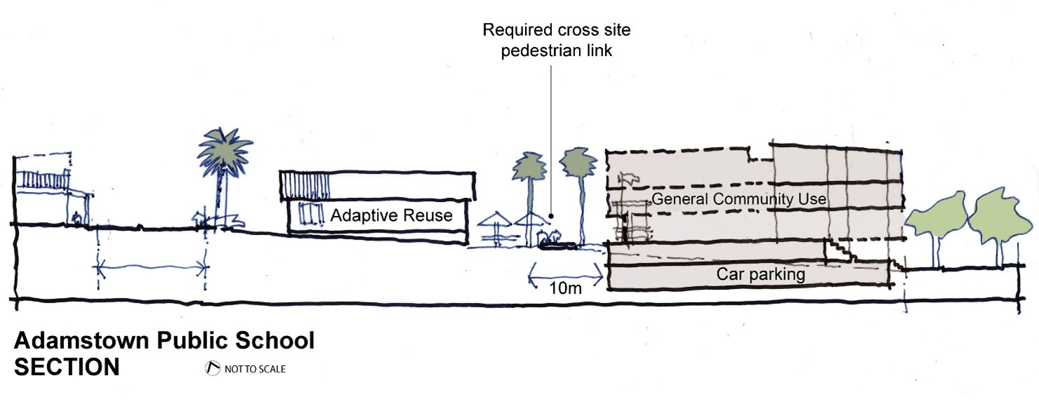 Figure E8.07: Adamstown public school section
Council library site
5. Redevelopment of Council’s existing library site, at the corner of Brunker Road and Victoria Street, incorporates a new formalised civic space that provides opportunities for gathering and outdoor dining, as shown in Figure E8.08.
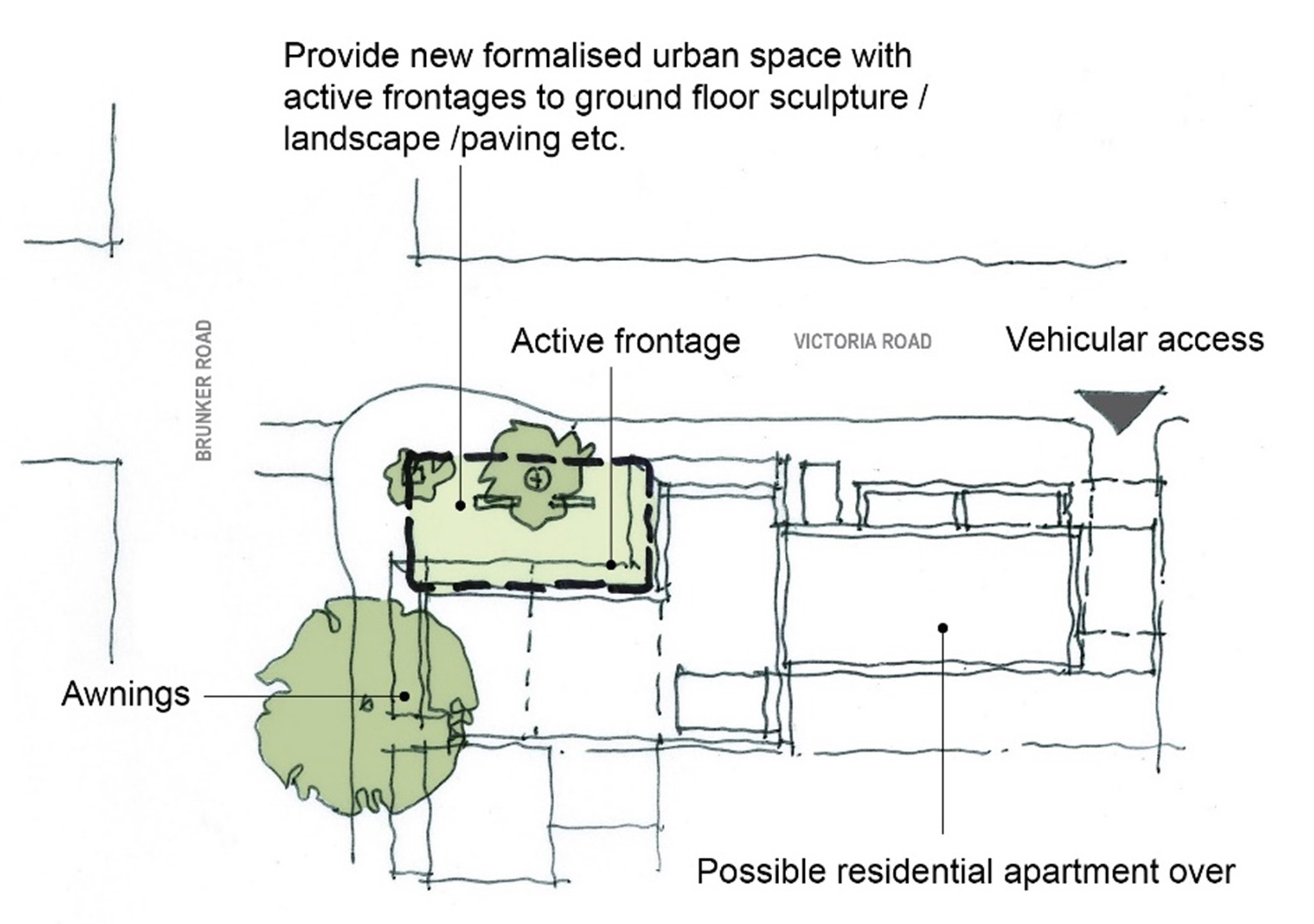 Figure E8.08: Adamstown library plan
 Objectives
- Incorporate publicly accessible art into significant development to enhance the sense of place and cultural identity.
- Ensure that publicly accessible art is located in appropriate areas to optimise recognition, amenity, and safety.
- Utilise publicly accessible artworks to interpret heritage components, recognise former uses of large development sites and reflect the desired contemporary character of a place.
- Recognise and celebrate indigenous and non-indigenous cultural heritage.
- Ensure publicly accessible artwork is easy to maintain.
Controls
- Development over $5 million must contribute art that is publicly accessible.
- Development required to provide publicly accessible art (in accordance with control 1) must be accompanied by a public art strategy prepared by a suitable qualified person. The public art strategy is to be in accordance with any strategy/guideline that outlines CN and the Public Art Reference Group's (PARG) process and expectations. Confirmation on the provision of publicly accessible art is required from CN in conjunction with the PARG or similar committee.
- The inclusion of publicly accessible art should be considered early in the design process to enable the appropriate integration of art with the detailed fabric and form of architectural, place and landscape designs. Early consultation with CN and affiliated PARG (or similar committee) is recommended.
- Publicly accessible art should be readily visible from the street.
- Where publicly accessible art is incorporated into building facades, roof features, open spaces, walkways, building foyers, landscaping or infrastructure it should be easily recognisable as an artistic feature and labelled accordingly in a close and noticeable location.
- Publicly accessible art installations in laneways are encouraged, including creative lighting to activate the laneway at night.
- The artwork should not be climbable unless specifically designed as a play safe artwork.
- Applicants should work with a heritage consultant and/or a public artist to develop innovative ways to interpret heritage using publicly accessible art.
- Publicly accessible art should respond to the significance and character of the location and where appropriate, interpret indigenous and non-indigenous cultural heritage.
- Publicly accessible art should cover a diverse range of themes and mediums to provide visual amenity and encourage interaction.
- Publicly accessible art must be safe and durable with consideration to avoid sharp edges, protrusions at eye height, trip hazards, and prevention of vandalism and deterioration over time.
- A publicly accessible artwork maintenance plan is developed prior to the installation of each new publicly accessible artwork to ensure the effective management of artwork.
- Where art is permanent, use materials that are:
- appropriate to the landscape/environment
- resistant to vandalism
- durable and easily maintained.
| Note: Publicly accessible means the ability to be viewed or experienced from publicly accessible places. This may be within the building facade or within the front setback. Early discussions with CN on the design and placement of public art is encouraged. Wherever possible, publicly accessible art should be designed by local artists. The cost of publicly accessible art installations is to be 1% of the cost of construction of the development. |
Land to which this section applies
This section applies to all land identified in Figure E8.09.
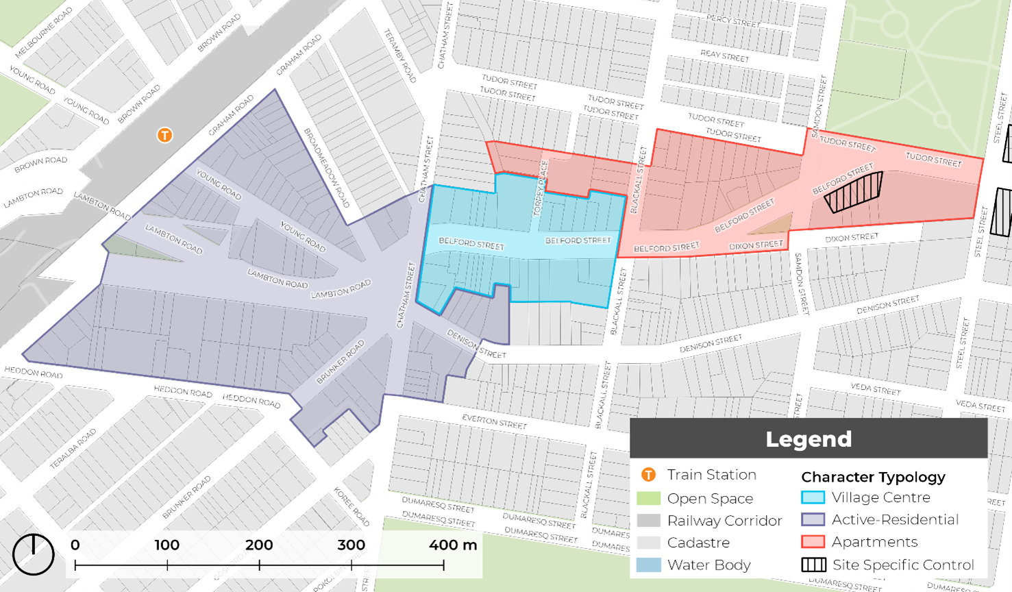 Figure E8.09: Broadmeadow renewal corridor area
Refer to the relevant setback and character typology for overarching development controls.
The Broadmeadow renewal corridor borders an area in Hamilton with significant heritage character known as Cameron’s Hill. The area is listed as a heritage conservation area (HCA) in Schedule 5 of the LEP and is roughly bounded by Tudor/Belford Streets, Steel Street, Everton Street and Blackall Street. The area has historical and aesthetic significance at a local level, with contributory examples of federation housing that once housed local mine managers and the Director of Education for the district, among others. Additionally, Denison Street was once the main street of Hamilton and contained several hotels where men socialised, and local sports teams were formed.
The blocks in Cameron's Hill HCA are much larger than those in the Hamilton Business Centre and Hamilton Residential Precinct HCAs, allowing for larger and more substantial homes that were generally built between 1844 and the 1930s. The single storey scale of housing stock, with a small number of two-storey residences in elevated positions, is an original defining feature of the area. Cameron's Hill was originally named Winship's Hill after James Barron Winship, a mine manager for Australian Agricultural Company (AA Company) in the 1860s, and was later renamed Cameron's Hill after James Cameron, the builder and owner of the Queen's Arms Hotel. Early in the 1900s, the AA Company subdivided its land on Cameron's Hill, leading to the appearance of a number of large Federation-style homes in the area. Cameron's Hill still has the AA Company mine manager's house, a state heritage item at 195 Denison Street which was built in 1849-50. Development in the renewal corridors must provide a sympathetic transition to Cameron’s Hill and conserve and maintain the heritage significance of the HCA, including the conservation and protection of associated fabric, settings and views.
| Note: Refer to Section E1 Built and landscape heritage and Section E2 Heritage conservation areas. |
Objectives
- Provide building setbacks that reflect established setbacks of buildings within the precinct.
- Reinforce a well defined street edge along all roads within the Nineways Centre and provide continuous built form.
- Provide a sense of enclosure to the Nineways centre through minimal setbacks.
- Provide space for tree planting and landscaping in desired areas.
- Ensure new development provides a sympathetic built form transition to adjacent low density residential areas.
- Ensure new development in the Cameron's Hill HCA and in the vicinity of the HCA conserves and maintains the heritage significance of the HCA, including the conservation and protection of associated fabric, settings and views.
Controls
- Front building setbacks must be consistent with those shown on Figure E8.10 and the relevant setbacks identified in sub-section 6.0 Character typologies.
- Upper level setbacks are encouraged to be used for open space and landscaping, provided privacy of adjoining uses are protected.
- New buildings in the Cameron's Hill HCA are to complement existing building envelopes, setbacks and building heights of heritage items and contributory buildings along Belford Street and Dixon Street.
- An alternative building setback from the character typologies listed in this section may only be accepted where it can demonstrate in urban design terms how the design solution was developed, how it was superior, and that the alternative setback:
- is more appropriate to the specific characteristics and context of the site and its surroundings, as compared to the setback requirements that have been assigned
- will not adversely affect the amenity of surrounding properties or the wider community
- meets the overall objectives of the section in terms of built form, scale, and bulk
- is consistent with good design principles and the desired character of the area.
| Note: Any proposed alternative setback must be submitted to CN for review and approval. The proponent will be required to provide detailed design drawings, elevations, and a written justification for the alternative setback. CN will consider the proposed alternative setback against the criteria outlined in this control and may approve, approve with conditions, or reject the proposal. A pre-DA meeting with CN is encouraged. |
 Figure E8.10: Broadmeadow building setback map
Objectives
- Provide consistent awnings along active frontages.
- Increase urban tree canopy cover.
- Manage the interface between street trees and awnings.
- Ensure that awnings, street trees and street infrastructure (such as power poles, street lighting, bus stops, drainage and telecommunication pits) are coordinated in their design and that their placement does not obstruct the public domain.
Controls
These controls should be read in conjunction with Section C10 Street awnings and balconies.
- Awnings must be provided in accordance with Figure E8.12.
- Awnings are to be consistent with Figure E8.11.
- The underside of an awning must be no lower than 3m above the footpath.
- As shown in Figure E8.11, the depth of an awning is determined by the footpath width to allow appropriate space for planting, street furniture and lighting.
- Continuous awnings must be provided to all active frontages. Breaks in awnings may be permitted for residential lobbies for legibility and for existing street trees.
- New awnings should respond to existing awnings in terms of width, height and material. Awning material preference should complement heritage or period facades with similar materials, signage and colour treatments.
- Awnings on Primary Streets should provide a continuous awning for the entire length of the frontage. Breaks in awnings may be permitted for residential lobbies for legibility and for existing street trees.
- Awnings on Secondary Streets should provide a continuation of the awning on the Primary Street, covering any active frontage for an appropriate distance relative to length of development.
- Where a proposed street tree is indicated on Figure E8.12, comprehensive redevelopment should provide new street tree planting, as per C3 Vegetation preservation and care and The Newcastle Urban Forest Technical Manual. Alternative tree locations and additional planting will be considered on merit.
| Note: The proposed tree locations are dynamic and provided as a guide. Development may consider street blister or vault planting for street trees where continuous awnings are prescribed. |
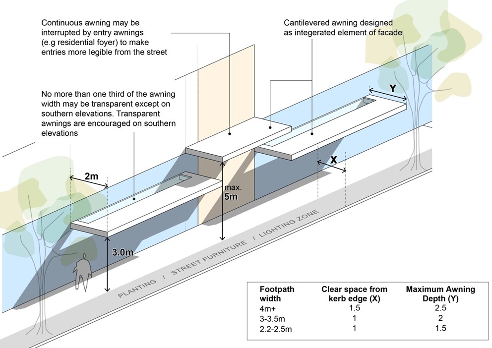 Figure E8.11: Awnings diagram
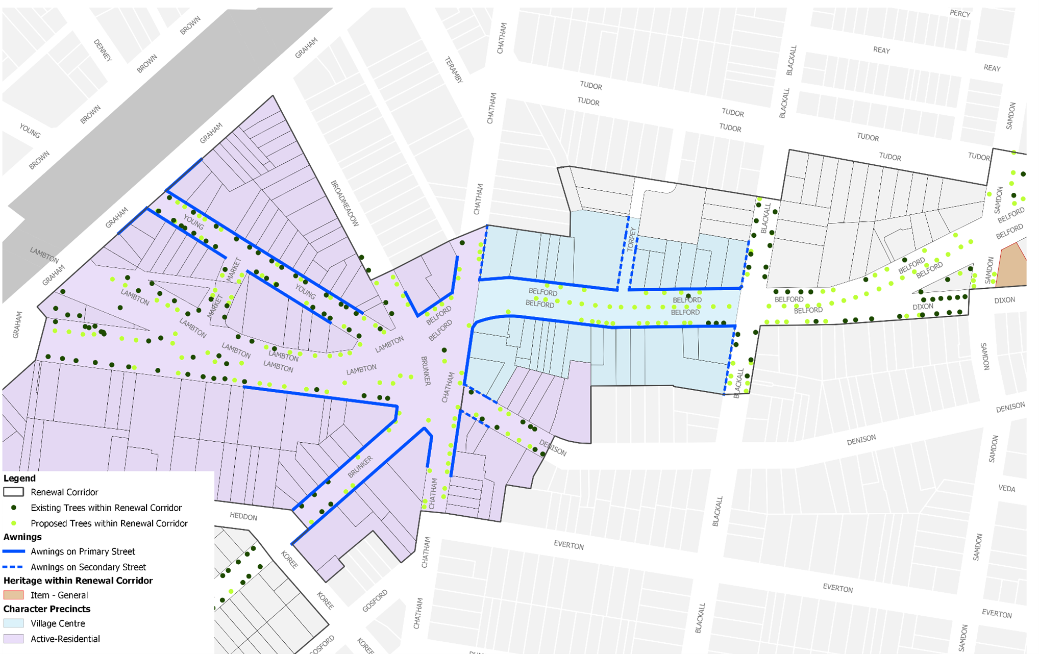 Figure E8.12: Broadmeadow street tree and awning map
Objectives
- Provide sufficient and discreet on-site car parking.
- Reduce potential vehicle and pedestrian conflict.
- Prioritise clear and simple vehicular access from side streets and rear access lanes
- Maximise opportunities for walking and cycling and where possible.
Controls
- Garages and car parks are located at the rear of sites.
- Access to be from side and rear streets.
- Car parking is provided in accordance with C1 Traffic, parking and access
- At-grade (ground level) car parking shall only be provided where:
- set back behind other uses that provide activation to street edge
- under cover, integrated into the built form, and covered by upper levels of development or upper level open space/landscaping provision
- ceiling heights and floor levels allow for future adaption to other uses
- not within building setbacks
- not impeding on minimum on site landscape requirements.
- Vehicle Access must be provided in accordance with Figure E8.13.
- Development is to provide footpaths for the full width of any site frontage. Where the proposed footpath will adjoin and connect to an existing or approved footpath on an adjoining site, the width of the proposed footpath is to match this footpath width. See C2 Movement networks for detail.
Objectives
- Incorporate publicly accessible art into significant development to enhance the sense of place and cultural identity.
- Ensure that publicly accessible art is located in appropriate areas to optimise recognition, amenity, and safety.
- Utilise publicly accessible artworks to interpret heritage components, recognise former uses of large development sites and reflect the desired contemporary character of a place.
- Recognise and celebrate indigenous and non-indigenous cultural heritage.
- Ensure publicly accessible artwork is easy to maintain.
Controls
- Development valued over $5 million must contribute art that is publicly accessible.
- Development required to provide publicly accessible art (in accordance with control 1) must be accompanied by a public art strategy prepared by a suitable qualified person. The public art strategy is to be in accordance with any strategy/guideline that outlines CN and the Public Art Reference Group's (PARG) process and expectations. Confirmation on the provision of publicly accessible art is required from CN in conjunction with the PARG or similar committee.
- The inclusion of publicly accessible art should be considered early in the design process to enable the appropriate integration of art with the detailed fabric and form of architectural, place and landscape designs. Early consultation with CN and affiliated PARG (or similar committee) is recommended.
- Publicly accessible art should be readily visible from the street.
- Where publicly accessible art is incorporated into building facades, roof features, open spaces, walkways, building foyers, landscaping or infrastructure it should be easily recognisable as an artistic feature and labelled accordingly in a close and noticeable location.
- Publicly accessible art installations in laneways are encouraged, including creative lighting to activate the laneway at night.
- The artwork should not be climbable unless specifically designed as a play safe artwork.
- Applicants should work with a heritage consultant and/or a public artist to develop innovative ways to interpret heritage using publicly accessible art.
- Publicly accessible art should respond to the significance and character of the location and where appropriate, interpret indigenous and non-indigenous cultural heritage.
- Publicly accessible art should cover a diverse range of themes and mediums to provide visual amenity and encourage interaction.
- Publicly accessible art must be safe and durable with consideration to avoid sharp edges, protrusions at eye height, trip hazards, and prevention of vandalism and deterioration over time.
- A publicly accessible artwork maintenance plan is developed prior to the installation of each new publicly accessible artwork to ensure the effective management of artwork.
- Where art is permanent, use materials that are:
- appropriate to the landscape/environment
- resistant to vandalism
- durable and easily maintained.
| Note: Publicly accessible means the ability to be viewed or experienced from publicly accessible places. This may be within the building facade or within the front setback. Early discussions with CN on the design and placement of public art is encouraged. Wherever possible, publicly accessible art should be designed by local artists. The cost of publicly accessible art installations is to be 1% of the cost of construction of the development. |
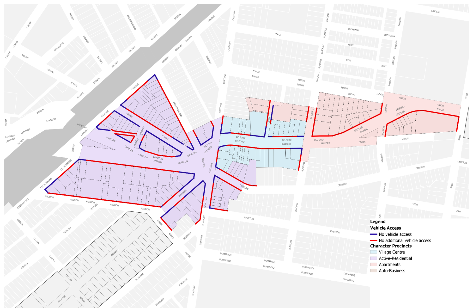 Figure E8.13: Broadmeadow vehicle access map
Land to which this section applies
This section applies to all land identified in Figure E8.15.
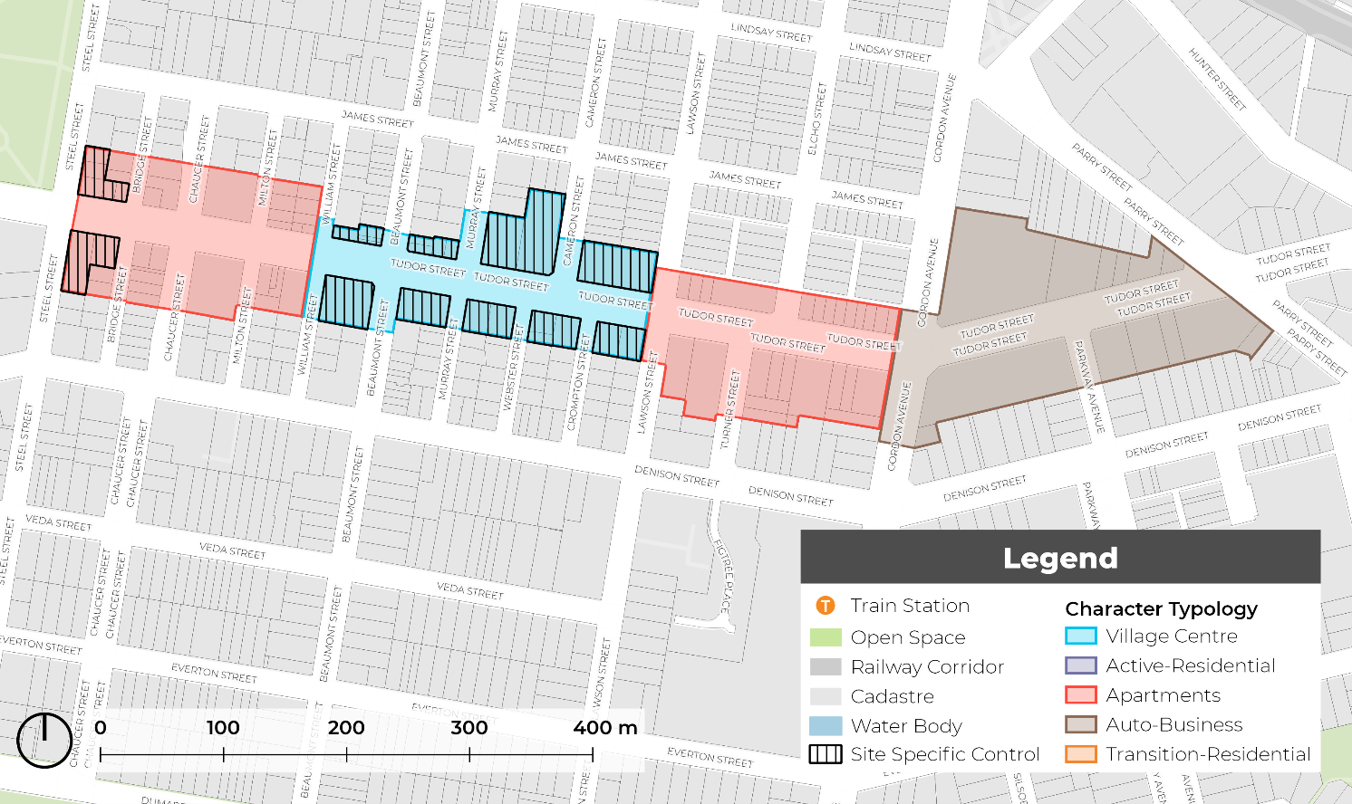 Figure E8.15: Hamilton renewal corridor area
Refer to the relevant setback and character typology for overarching development controls.
Objectives
- Reinforce and maintain a well defined street edge along Brunker and Glebe Roads.
- Extend and reinforce a strong street edge built form along Tudor Street.
- Provide space for tree planting and landscaping in desired areas.
Controls
- Front building setbacks must be consistent with those shown on Figure E8.16 and the relevant setbacks identified in sub-section 6.0 Character typologies.
- Upper level setbacks are encouraged to be used for open space and landscaping, provided privacy of adjoining uses are protected.
- An alternative building setback from the character typologies listed in this section may only be accepted where it can demonstrate in urban design terms how the design solution was developed, how it was superior, and that the alternative setback:
- is more appropriate to the specific characteristics and context of the site and its surroundings, as compared to the setback requirements that have been assigned
- will not adversely affect the amenity of surrounding properties or the wider community
- meets the overall objectives of the section in terms of built form, scale, and bulk
- is consistent with good design principles and the desired character of the area.
| Note: Any proposed alternative setback must be submitted to the council for review and approval. The proponent will be required to provide detailed design drawings, elevations, and a written justification for the alternative setback. CN will consider the proposed alternative setback against the criteria outlined in this control and may approve, approve with conditions, or reject the proposal. A pre-DA meeting with council officers is encouraged when proposing an alternative setback. |
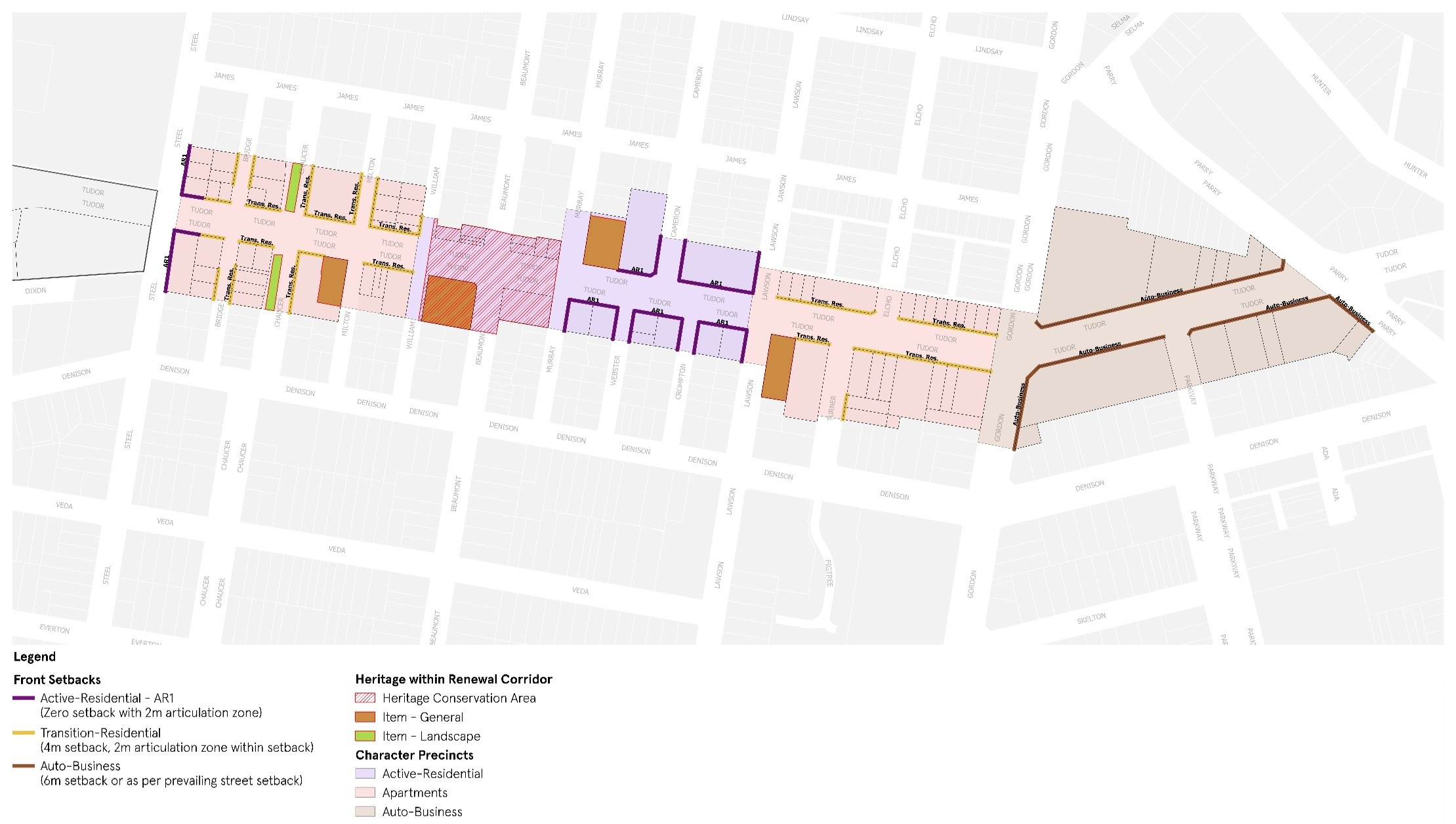 Figure E8.16: Hamilton building setback map
Objectives
- Provide consistent awnings along active frontages.
- Increase urban tree canopy cover.
- Manage the interface between street trees and awnings.
- Ensure that awnings, street trees and street infrastructure (such as power poles, street lighting, bus stops, drainage and telecommunication pits) are coordinated in their design and that their placement does not obstruct the public domain.
Controls
These controls should be read in conjunction with Section C10 Street awnings and balconies.
- Awnings must be provided in accordance with Figure E8.18.
- Awnings are to be consistent with Figure E8.17.
- The underside of an awning must be no lower than 3m above the footpath.
- As shown in Figure E8.17, the depth of an awning is determined by the footpath width to allow appropriate space for planting, street furniture and lighting.
- Continuous awnings must be provided to all active frontages. Breaks in awnings may be permitted for residential lobbies for legibility and for existing street trees.
- New awnings should respond to existing awnings in terms of width, height and material. Awning material preference should compliment heritage or period facades with similar materials, signage and colour treatments.
- Awnings on Primary Streets should provide a continuous awning for the entire length of the frontage. Breaks in awnings may be permitted for residential lobbies for legibility and for existing street trees.
- Awnings on Secondary Streets should provide a continuation of the awning on the Primary Street, covering any active frontage for an appropriate distance relative to length of development.
- Where a proposed street tree is indicated on Figure E8.18, comprehensive redevelopment should provide new street tree planting, as per C3 Vegetation preservation and care and The Newcastle Urban Forest Technical Manual. Alternative tree locations and additional planting will be considered on merit.
| Note: The proposed tree locations are dynamic and provided as a guide. Development may consider street blister or vault planting for street trees where continuous awnings are prescribed. |
 Figure E8.17: Awnings diagram
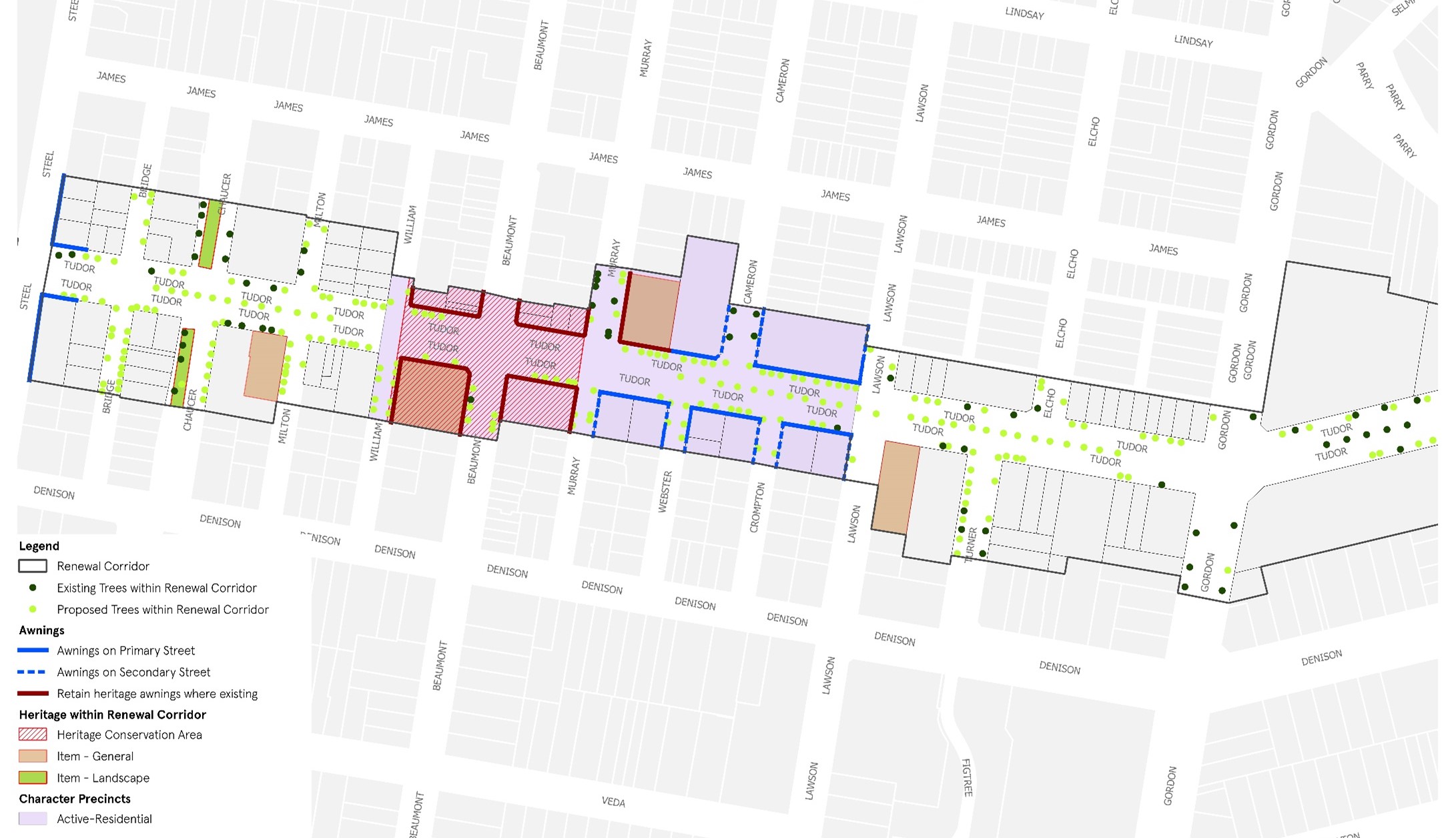
Figure E8.18: Hamilton street tree and awning map
Objectives
- Reduce potential vehicle and pedestrian conflict along site frontages to Tudor Street.
- Provide clear and simple vehicular access from side streets and rear access lanes.
- Restrict direct vehicular access to Tudor Street.
- Provide sufficient off-street car parking.
- Minimise impacts from car parking on the streetscape and open space areas.
- Maximise opportunities for walking and cycling and where possible.
Controls
General controls applying to all development to which this section applies
- Vehicle access for development is restricted to the side roads and rear lanes, where possible.
- Vehicular access across the footpath to allow direct vehicular access onto Tudor Street is only to occur where no alternate option is available and the development site has a minimum width of 24m. Consolidation of lots may be necessary to achieve this minimum width.
- Car parking is provided as per C1 Traffic, Parking and Access.
- Vehicle accesses are recessed from building facades.
- At-grade (ground level) car parking is only provided where:
- it is set back behind other uses that provide activation to street edge
- it is integrated into the built form and covered by upper levels of development or upper level open space/landscaping provision
- ceiling heights and floor levels allow for future adaption to other uses
- it is not within building setbacks
- it is not impeding on ability to meet minimum on site landscape requirements.
- Car parking facilities are screened from Tudor Street through building design.
- Development is to provide footpaths for the full width of any site frontage. Where the proposed footpath will adjoin and connect to an existing or approved footpath on an adjoining site, the width of the proposed footpath is to match this footpath width. See C2 Movement networks for detail.
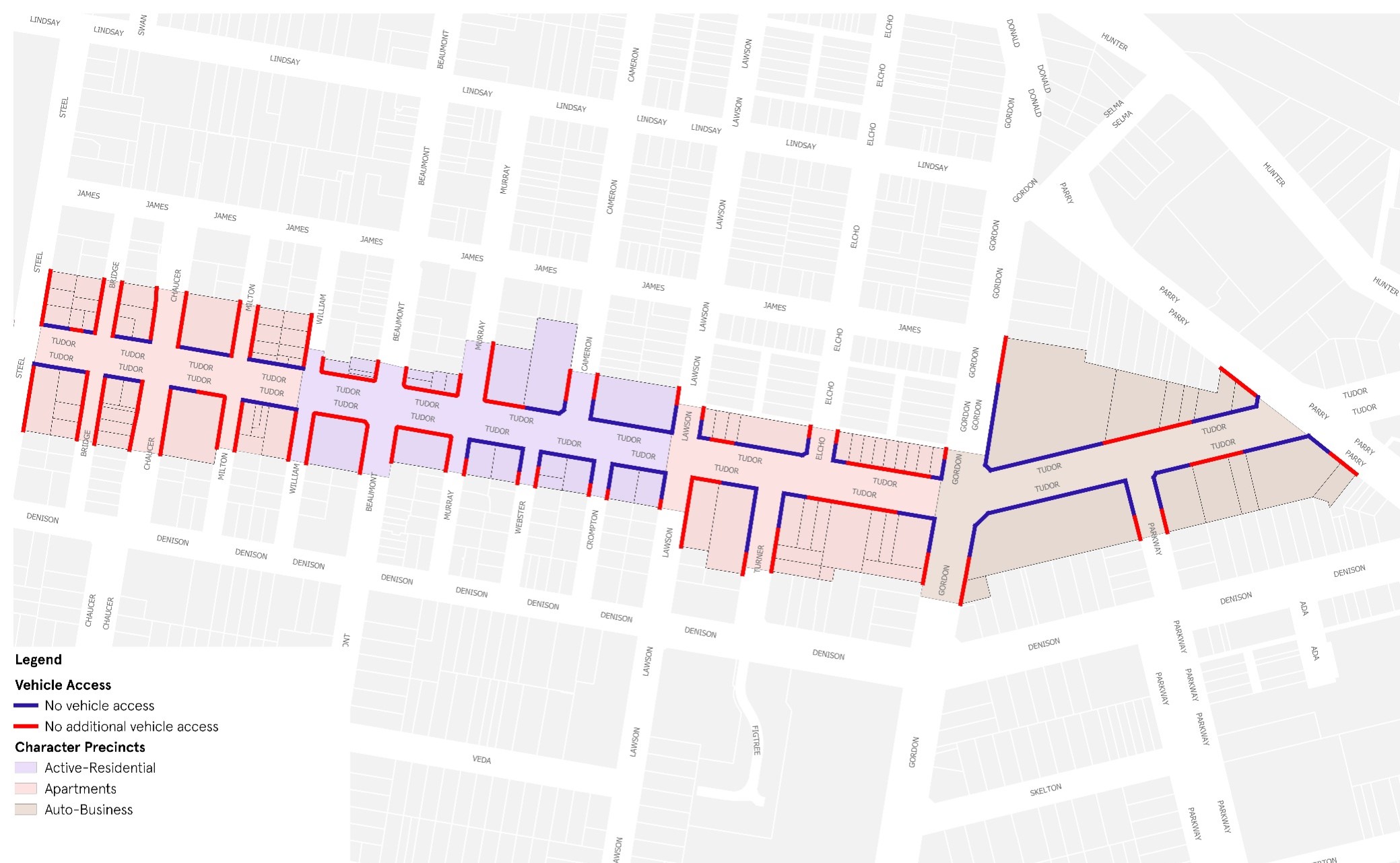
Figure E8.19: Hamilton vehicle access map
Objectives
- Guide development outcomes on specific sites.
- Establish gateways to the corridor through built form and landscape improvements.
Controls
Envisaged facade treatment for Village Centre character precinct
- Facade treatment should incorporate elements that create visual articulation to the building mass. These may be achieved within 6m - 8m bays as shown in Figure E8.20.
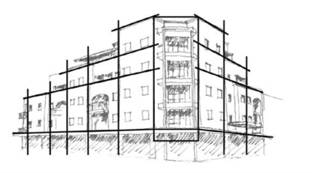 Figure E8.20: Facade treatment for Village Centre character precinct
Gateway development at the corner of Tudor and Steel Streets
2. Development at the corner of Tudor and Steel Streets should establish a ‘gateway’ style mixed use development, with clearly define street corners. A ‘gateway’ development should have visual prominence and clearly defined the street walls.
Objectives
- Incorporate publicly accessible art into significant development to enhance the sense of place and cultural identity.
- Ensure that publicly accessible art is located in appropriate areas to optimise recognition, amenity, and safety.
- Utilise publicly accessible artworks to interpret heritage components, recognise former uses of large development sites and reflect the desired contemporary character of a place.
- Recognise and celebrate indigenous and non-indigenous cultural heritage.
- Ensure publicly accessible artwork is easy to maintain.
Controls
- Development valued over $5 million must contribute art that is publicly accessible.
- Development required to provide publicly accessible art (in accordance with control 1) must be accompanied by a public art strategy prepared by a suitable qualified person. The public art strategy is to be in accordance with any strategy/guideline that outlines CN and the Public Art Reference Group's (PARG) process and expectations. Confirmation on the provision of publicly accessible art is required from CN in conjunction with the PARG or similar committee.
- The inclusion of publicly accessible art should be considered early in the design process to enable the appropriate integration of art with the detailed fabric and form of architectural, place and landscape designs. Early consultation with CN and affiliated PARG (or similar committee) is recommended.
- Publicly accessible art should be readily visible from the street.
- Where publicly accessible art is incorporated into building facades, roof features, open spaces, walkways, building foyers, landscaping or infrastructure it should be easily recognisable as an artistic feature and labelled accordingly in a close and noticeable location.
- Publicly accessible art installations in laneways are encouraged, including creative lighting to activate the laneway at night.
- The artwork should not be climbable unless specifically designed as a play safe artwork.
- Applicants should work with a heritage consultant and/or a public artist to develop innovative ways to interpret heritage using publicly accessible art.
- Publicly accessible art should respond to the significance and character of the location and where appropriate, interpret indigenous and non-indigenous cultural heritage.
- Publicly accessible art should cover a diverse range of themes and mediums to provide visual amenity and encourage interaction.
- Publicly accessible art must be safe and durable with consideration to avoid sharp edges, protrusions at eye height, trip hazards, and prevention of vandalism and deterioration over time.
- A publicly accessible artwork maintenance plan is developed prior to the installation of each new publicly accessible artwork to ensure the effective management of artwork.
- Where art is permanent, use materials that are:
- appropriate to the landscape/environment
- resistant to vandalism
- durable and easily maintained.
| Note: Publicly accessible means the ability to be viewed or experienced from publicly accessible places. This may be within the building facade or within the front setback. Early discussions with CN on the design and placement of public art is encouraged. Wherever possible, publicly accessible art should be designed by local artists. The cost of publicly accessible art installations is to be 1% of the cost of construction of the development. |
Land to which this section applies
This section applies to all land identified in Figure E8.21.
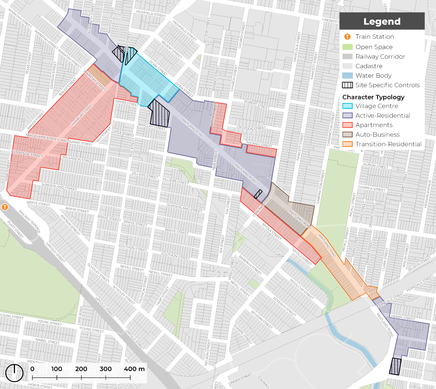 Figure E8.21: Mayfield renewal corridor area
Refer to the relevant setback and character typology for overarching development controls.
Objectives
- Reinforce and maintain a well defined street edge along Maitland Road in desired locations.
- Extend and reinforce a strong street edge built form along Maitland Road.
- Provide space for tree planting and landscaping in desired areas.
Controls
- Front building setbacks must be consistent with those shown on Figure E8.22 and the relevant setbacks identified in sub-section 6.0 Character typologies.
- Upper level setbacks are encouraged to be used for open space and landscaping, provided privacy of adjoining uses are protected.
- An alternative building setback from the character typologies listed in this section may only be accepted where it can demonstrate in urban design terms how the design solution was developed, how it was superior, and that the alternative setback:
- is more appropriate to the specific characteristics and context of the site and its surroundings, as compared to the setback requirements that have been assigned
- will not adversely affect the amenity of surrounding properties or the wider community
- meets the overall objectives of the section in terms of built form, scale, and bulk
- is consistent with good design principles and the desired character of the area.
| Note: Any proposed alternative setback must be submitted to the council for review and approval. The proponent will be required to provide detailed design drawings, elevations, and a written justification for the alternative setback. CN will consider the proposed alternative setback against the criteria outlined in this control and may approve, approve with conditions, or reject the proposal. A pre-DA meeting with CN is encouraged. |
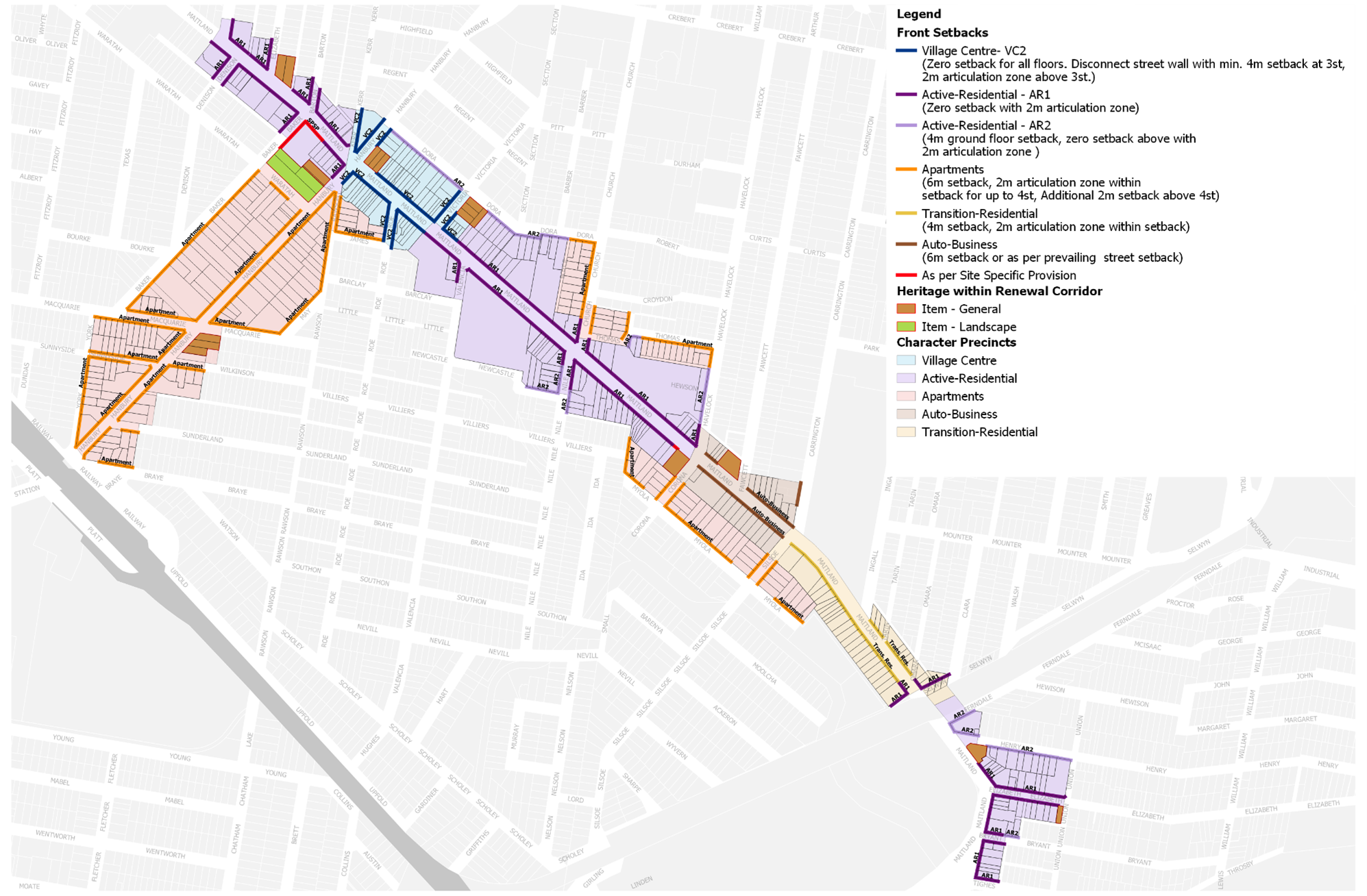
Figure E8.22: Mayfield building setback map
Objectives
- Provide consistent awnings along active frontages.
- Increase urban tree canopy cover.
- Manage the interface between street trees and awnings.
- Ensure that awnings, street trees and street infrastructure (such as power poles, street lighting, bus stops, drainage and telecommunication pits) are coordinated in their design and that their placement does not obstruct the public domain.
Controls
These controls should be read in conjunction with Section C10 Street awnings and balconies.
- Awnings must be provided in accordance with Figure E8.24.
- Awnings are to be consistent with Figure E8.23.
- The underside of an awning must be no lower than 3m above the footpath.
- As shown in Figure E8.23, the depth of an awning is determined by the footpath width to allow appropriate space for planting, street furniture and lighting.
- Continuous awnings must be provided to all active frontages. Breaks in awnings may be permitted for residential lobbies for legibility and for existing street trees.
- New awnings should respond to existing awnings in terms of width, height and material. Awning material preference should compliment heritage or period facades with similar materials, signage and colour treatments.
- Awnings on Primary Streets should provide a continuous awning for the entire length of the frontage. Breaks in awnings may be permitted for residential lobbies for legibility and for existing street trees.
- Awnings on Secondary Streets should provide a continuation of the awning on the Primary Street, covering any active frontage for an appropriate distance relative to length of development.
- Where a proposed street tree is indicated on Figure E8.24, comprehensive redevelopment should provide new street tree planting, as per C3 Vegetation preservation and care and The Newcastle Urban Forest Technical Manual. Alternative tree locations and additional planting will be considered on merit.
| Note: The proposed tree locations are dynamic and provided as a guide. Development may consider street blister or vault planting for street trees where continuous awnings are prescribed. |
 Figure E8.23: Awnings diagram
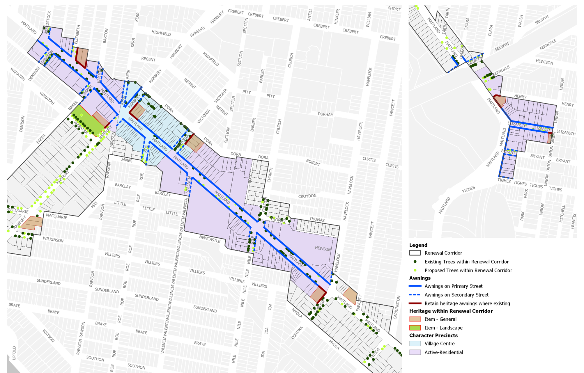
Figure E8.24: Mayfield street tree and awning map
Objectives
- Minimise vehicles directly accessing onto Maitland Road from new development.
- Provide sufficient off-street car parking.
- Minimise impact from car parking on the streetscape and outdoor areas on site.
- Maximise opportunities for walking and cycling and where possible.
Controls
General controls applying to all development to which this section applies
- Where possible, site access only to be provided off secondary streets and rear laneways, as identified on Figure E8.25.
- Vehicle access may only be provided directly onto Maitland Road where no alternate access exists and where sites have a minimum frontage of 24m.
- Existing laneways and right-of-ways to be retained for access by new and existing development.
- New public laneways are to be provided as shown on Figure E8.25 and dedicated to Council. The exact location of these may be negotiated at the DA stage.
- Where negotiated prior to determination of a development proposal, such laneways may be incorporated into the development or allow development of their airspace but only where this allows for unrestricted public access. Vehicle entrances are not to dominate the streetscape and are to be recessed from building facades.
- Car parking is provided as per Section C1Traffic, parking and access.
- At-grade (ground level) car parking only to be provided where:
- it is set back behind other uses that provide activation to street edge
- it is under cover and integrated into the built form and covered by upper levels of development or upper level open space/landscaping provision
- ceiling heights and floor levels allow for future adaption to other uses
- it is not within building setbacks
- it is not impeding on ability to meet minimum on site landscape requirements.
- Above ground car parking facilities to be located to the rear of development along Maitland Road and screened from any street frontages by use of built form, architectural screens or landscaping.
- Driveways directly accessing Maitland Road, where necessary, are not to result in queuing across footpath.
- Enhance safety and amenity of bus stops by encouraging adjoining active uses, passive surveillance, and weather protection.
- No vehicle access is provided directly to/from Maitland Road unless:
- no access is available to Corona or Silsoe Streets
- adjoining land has not yet been redeveloped to include laneway access
- development will not result in additional access to Maitland Road
- access connects to rear laneway provided (on site) in redevelopment; and such access becomes one-way upon rear lane access connecting to either Corona or Silsoe Streets.
- Redevelopment of the Mayfield Hotel and Retail strip on Maitland Road between Baker and Hanbury Street is to include a new street, connecting Baker and Hanbury Streets. Car parking should be provided at sub-ground level or within a multilevel facility that is not visible from the public domain.
- Development is to provide footpaths for the full width of any site frontage. Where the proposed footpath will adjoin and connect to an existing or approved footpath on an adjoining site, the width of the proposed footpath is to match this footpath width. See C2 Movement Networks for detail.
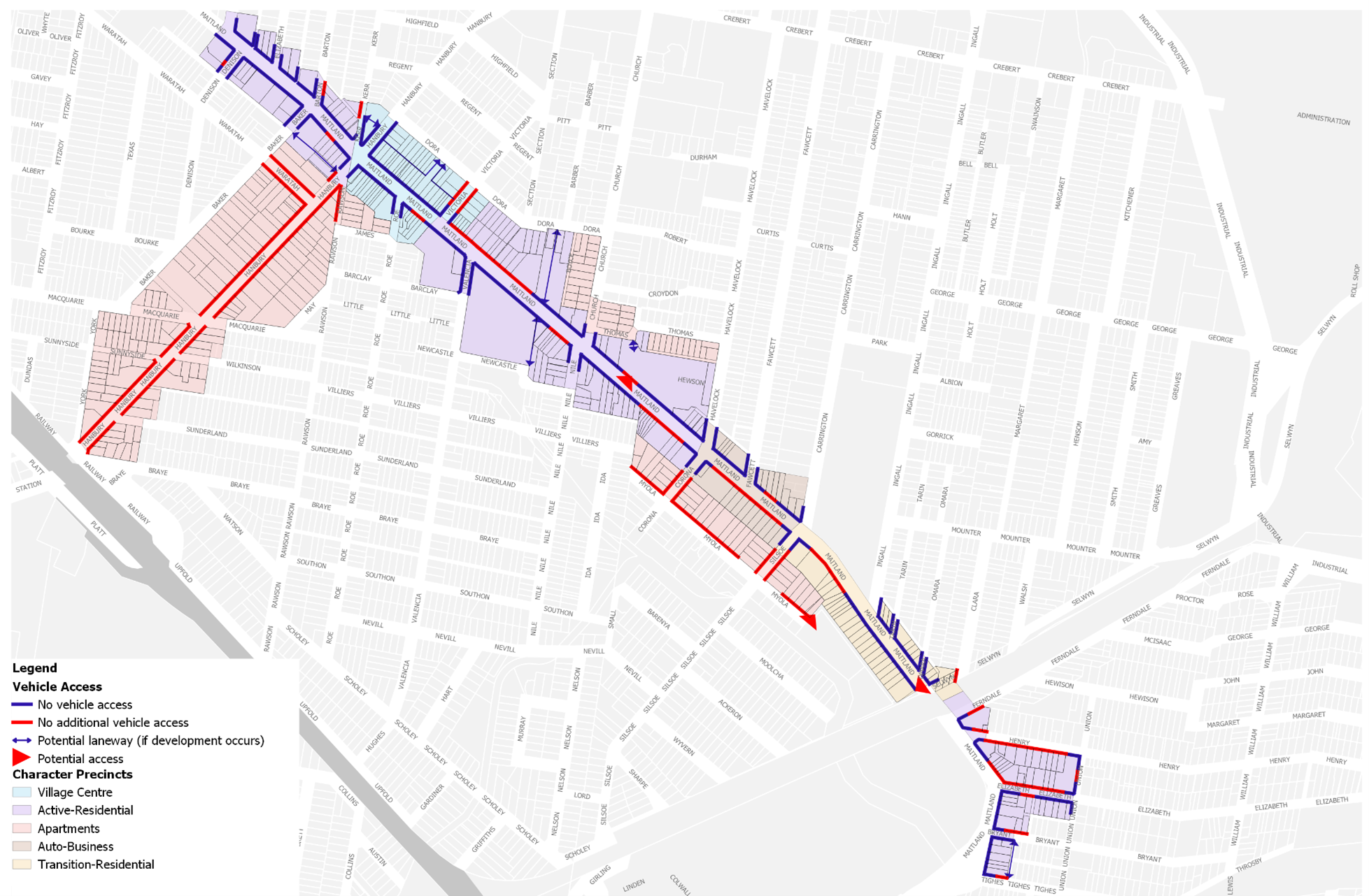
Figure E8.25: Mayfield vehicle access map
Objectives
- Guide development outcomes on specific sites.
- Ensure good design outcomes that respect local character and heritage.
Controls
Development adjacent to the Coliseum
The Coliseum at 116-122 Maitland Road, Mayfield is a locally significant single storey commercial building located on an important corner site. Built in 1921, it is an intact example of commercial buildings from this era.
- Development adjoining the ‘Coliseum’ heritage item should be set back for 12m along the Maitland Road street frontage, at a depth of at least 6m (see Figure E8.26). Setbacks are to contain landscaping that complements the character and scale of this heritage item.
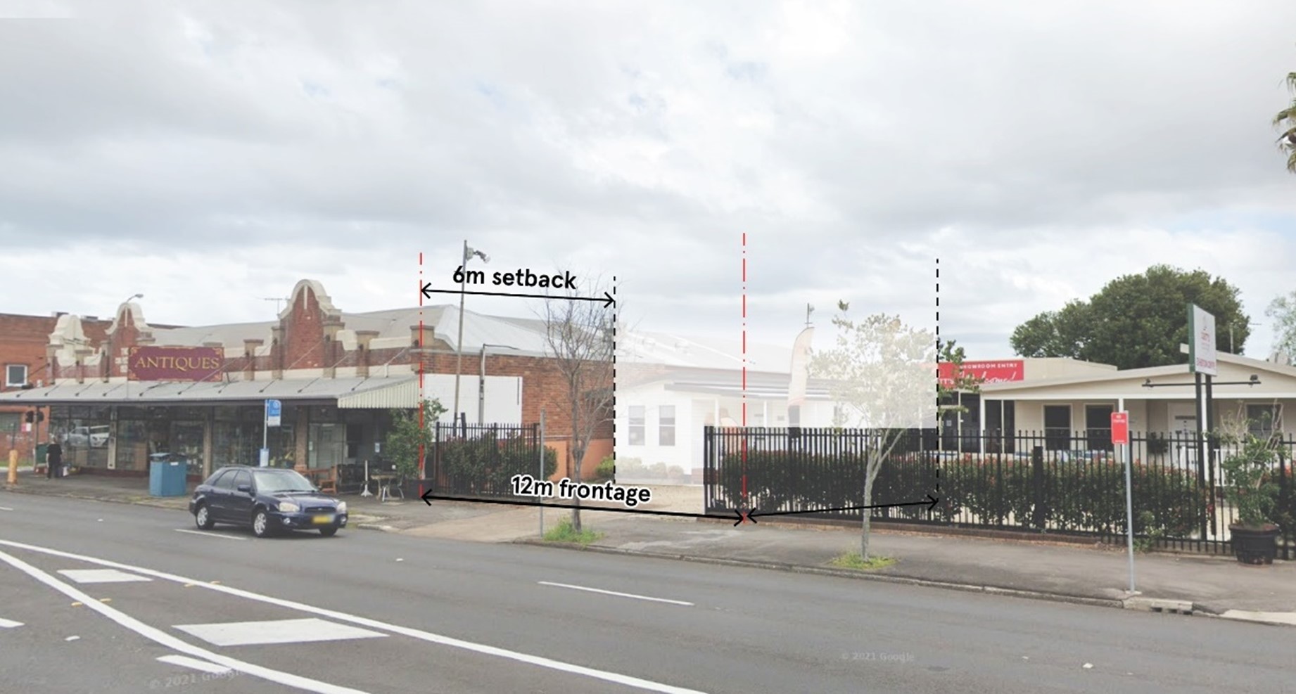 Figure E8.26: Development adjacent to the Coliseum
Entry to Corridor in Tighes HIll
Tighes Hill is the southern gateway to the Mayfield renewal corridor.
2. Redevelopment of the 161 Maitland Road will require widening of existing rear laneway by a minimum of 5m. This dimension to include a 2m wide footpath Figure E8.27.
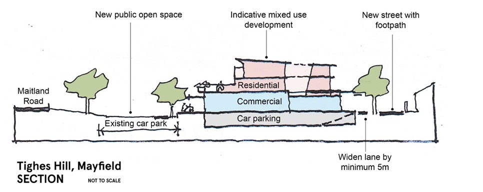 Figure E8.27: Section of landscape requirements for entry to corridor in Tighes Hill
Mayfield retail core (Woolworths and Aldi)
3. Redevelopment of the Aldi site in Mayfield should be consistent with Figure E8.28.
4. Redevelopment of the Aldi site in Mayfield should also include a new street between Newcastle Street and Maitland Road, which provides for pedestrian-based activity and improved links to public open space along Newcastle Street.
5. Future redevelopment of current Aldi site and adjacent corner site should include active street frontages and a zero front setback to Maitland Road.
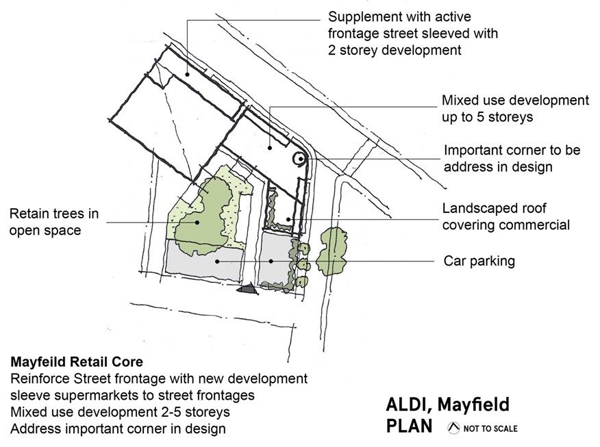 Figure E8.28: Potential redevelopment the corner site at Maitland Road and Valencia Street
Mayfield library site
6. Future redevelopment of the existing Mayfield library site should include a new civic square/forecourt containing both hard and soft landscape elements including public art and shade trees. To facilitate this, part of Kerr Street should be transformed into a shared zone and realigned to connect with Hanbury Street and the existing rear lane, as shown in Figure E8.29.
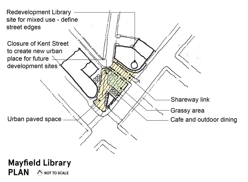 Figure E8.29: Landscape requirements for redevelopment of Mayfield library site
Objectives
- Incorporate publicly accessible art into significant development to enhance the sense of place and cultural identity.
- Ensure that publicly accessible art is located in appropriate areas to optimise recognition, amenity, and safety.
- Utilise publicly accessible artworks to interpret heritage components, recognise former uses of large development sites and reflect the desired contemporary character of a place.
- Recognise and celebrate indigenous and non-indigenous cultural heritage.
- Ensure publicly accessible artwork is easy to maintain.
Controls
- Development over $5 million must contribute art that is publicly accessible.
- Development required to provide publicly accessible art (in accordance with control 1) must be accompanied by a public art strategy prepared by a suitable qualified person. The public art strategy is to be in accordance with any strategy/guideline that outlines CN and the Public Art Reference Group's (PARG) process and expectations. Confirmation on the provision of publicly accessible art is required from CN in conjunction with the PARG or similar committee.
- The inclusion of publicly accessible art should be considered early in the design process to enable the appropriate integration of art with the detailed fabric and form of architectural, place and landscape designs. Early consultation with CN and affiliated PARG (or similar committee) is recommended.
- Publicly accessible art should be readily visible from the street.
- Where publicly accessible art is incorporated into building facades, roof features, open spaces, walkways, building foyers, landscaping or infrastructure it should be easily recognisable as an artistic feature and labelled accordingly in a close and noticeable location.
- Publicly accessible art installations in laneways are encouraged, including creative lighting to activate the laneway at night.
- The artwork should not be climbable unless specifically designed as a play safe artwork.
- Applicants should work with a heritage consultant and/or a public artist to develop innovative ways to interpret heritage using publicly accessible art.
- Publicly accessible art should respond to the significance and character of the location and where appropriate, interpret indigenous and non-indigenous cultural heritage.
- Publicly accessible art should cover a diverse range of themes and mediums to provide visual amenity and encourage interaction.
- Publicly accessible art must be safe and durable with consideration to avoid sharp edges, protrusions at eye height, trip hazards, and prevention of vandalism and deterioration over time.
- A publicly accessible artwork maintenance plan is developed prior to the installation of each new publicly accessible artwork to ensure the effective management of artwork.
- Where art is permanent, use materials that are:
- appropriate to the landscape/environment
- resistant to vandalism
- durable and easily maintained.
| Note: Publicly accessible means the ability to be viewed or experienced from publicly accessible places. This may be within the building facade or within the front setback. Early discussions with CN staff on the design and placement of public art is encouraged. Wherever possible, publicly accessible art should be designed by local artists. The cost of publicly accessible art installations is to be 1% of the cost of construction of the development. |
Land to which this section applies
This section applies to all land identified in Figure E8.30.
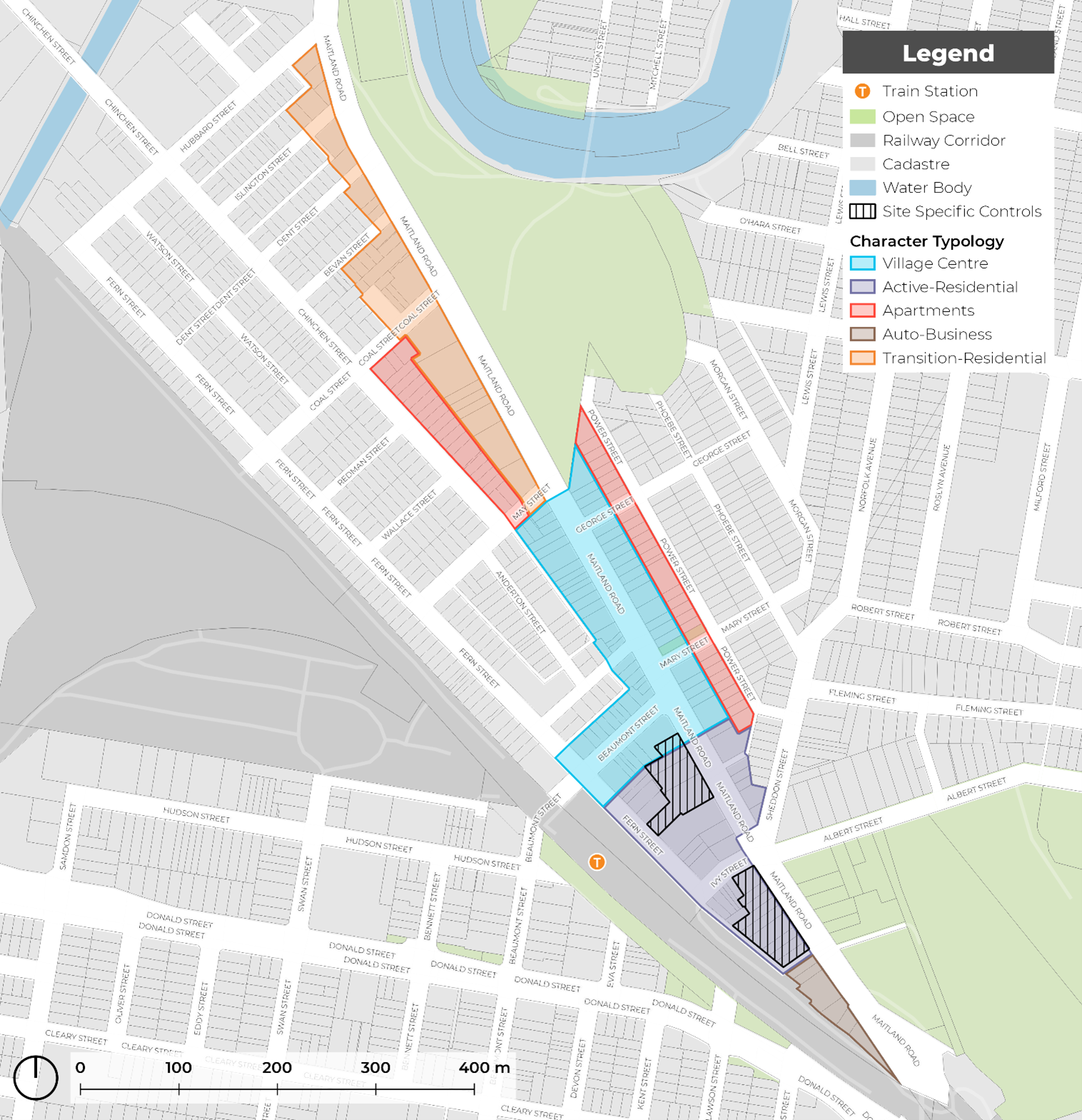 Figure E8.30: Islington renewal corridor area
Objectives
- Reinforce a consistent street edge and maintain the scale of facade along the street.
- Respect the adjoining residential precinct and commercial centre through the implementation of appropriate building setbacks at each interface.
- Provide space for tree planting and landscaping in desired areas.
Controls
- Front building setbacks must be consistent with those shown on Figure E8.31 and the relevant setbacks identified in sub-section 6.0 Character typologies.
- Upper level setbacks are encouraged to be used for open space and landscaping, provided privacy of adjoining uses are protected.
- An alternative building setback from the character typologies listed in this section may only be accepted where it can demonstrate in urban design terms how the design solution was developed, how it was superior, and that the alternative setback:
- is more appropriate to the specific characteristics and context of the site and its surroundings, as compared to the setback requirements that have been assigned
- will not adversely affect the amenity of surrounding properties or the wider community
- meets the overall objectives of the section in terms of built form, scale, and bulk
- is consistent with good design principles and the desired character of the area.
| Note: Any proposed alternative setback must be submitted to the council for review and approval. The proponent will be required to provide detailed design drawings, elevations, and a written justification for the alternative setback. Council will consider the proposed alternative setback against the criteria outlined in this control and may approve, approve with conditions, or reject the proposal. A pre-DA meeting with council officers is encouraged. |
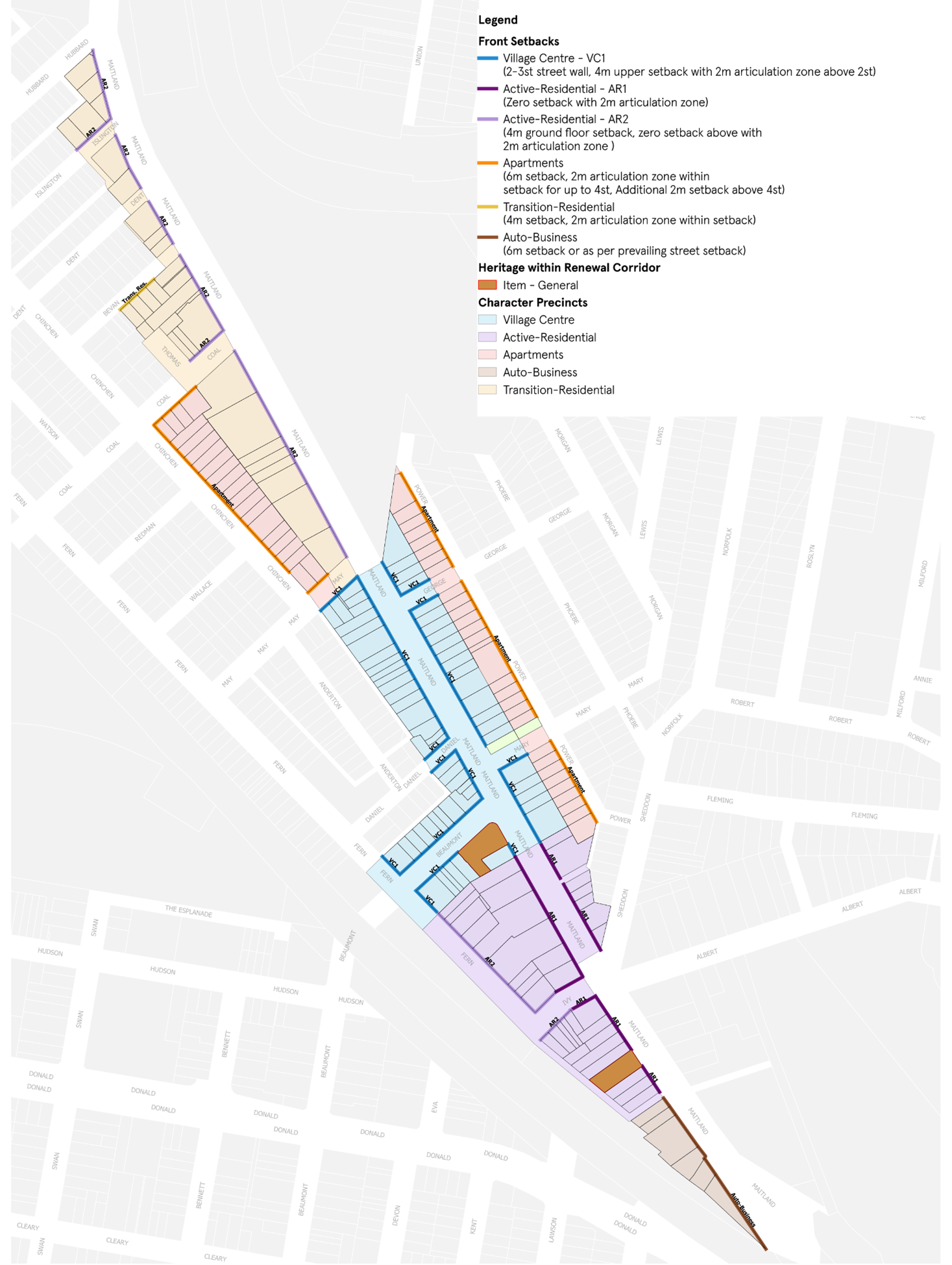 Figure E8.31: Islington building setback map
Objectives
- Provide consistent awnings along active frontages.
- Increase urban tree canopy cover.
- Manage the interface between street trees and awnings.
- Ensure that awnings, street trees and street infrastructure (such as power poles, street lighting, bus stops, drainage and telecommunication pits) are coordinated in their design and that their placement does not obstruct the public domain.
Controls
These controls should be read in conjunction with Section C10 Street awnings and balconies.
- Awnings must be provided in accordance with Figure E8.33.
- Awnings are to be consistent with Figure E8.32.
- The underside of an awning must be no lower than 3m above the footpath.
- As shown in Figure E8.32, the depth of an awning is determined by the footpath width to allow appropriate space for planting, street furniture and lighting.
- Continuous awnings must be provided to all active frontages. Breaks in awnings may be permitted for residential lobbies for legibility and for existing street trees.
- New awnings should respond to existing awnings in terms of width, height and material. Awning material preference should complement heritage or period facades with similar materials, signage and colour treatments.
- Awnings on Primary Streets should provide a continuous awning for the entire length of the frontage. Breaks in awnings may be permitted for residential lobbies for legibility and for existing street trees.
- Awnings on Secondary Streets should provide a continuation of the awning on the Primary Street, covering any active frontage for an appropriate distance relative to length of development.
- Where a proposed street tree is indicated on Figure E8.33, comprehensive redevelopment should provide new street tree planting, as per C3 Vegetation preservation and care and The Newcastle Urban Forest Technical Manual. Alternative tree locations and additional planting will be considered on merit.
| Note: The proposed tree locations are dynamic and provided as a guide. Development may consider street blister or vault planting for street trees where continuous awnings are prescribed. |
 Figure E8.32: Awnings diagram
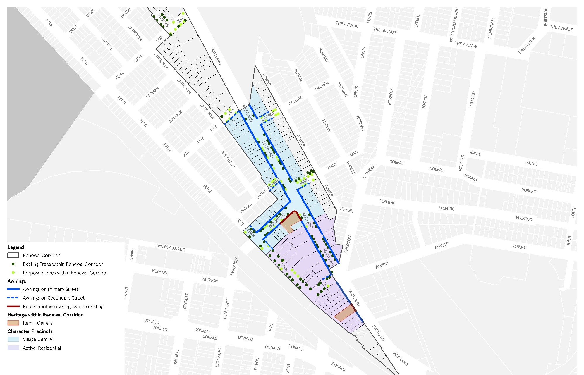
Figure E8.33: Islington street tree and awning map
Objectives
- Minimise vehicles directly accessing onto Maitland Road from new development.
- Provide sufficient off-street car parking.
- Minimise impact from car parking on the streetscape and outdoor areas on site.
- Maximise opportunities for walking and cycling and where possible.
Controls
General controls applying to all development to which this section applies
- Vehicular access must comply with Figure E8.34.
- Vehicular access onto Maitland Road is only to occur where no alternate option is available, and the development site has a minimum width of 24m.
- Vehicle entrances do not dominate the streetscape and should be recessed from building facades.
- Vehicular access to loading areas is restricted to side or rear streets and lanes, where these occur.
- Rear lanes to the south of Maitland Road should be the primary vehicular access point to redeveloped sites along the southern side of the corridor.
- Car parking is provided in accordance with C1 Traffic, Parking and Access.
- Development is to provide footpaths for the full width of any site frontage. Where the proposed footpath will adjoin and connect to an existing or approved footpath on an adjoining site, the width of the proposed footpath is to match this footpath width. See C2 Movement networks for detail.
- Sub-ground car parking is encouraged, however, where above-ground car parking is provided, it should be located to the rear of sites and appropriately screened from streets through the use of architectural screens, landscape or building forms.
- At grade (ground level) car parking is only provided where:
- set back behind other uses that provide activation to street edge
- under cover and integrated into the built form and covered by upper levels of development or upper level open space/landscaping provision
- ceiling heights and floor levels allow for future adaption to other uses
- not within building setbacks
- not impeding on ability to meet onsite landscape requirements.
The following controls apply to development in ‘Transition-Residential’ character typology
10. Existing rear lanes and streets, predominantly Hubbard, Coal and May Streets should be utilised for vehicle access points.
11. Pedestrian entrances should be predominantly from Maitland Road to activate the street, while vehicle access should be restricted to rear and side streets where possible.
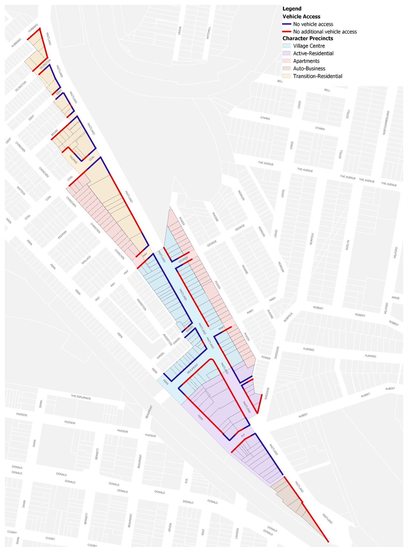 Figure E8.34: Islington vehicle access map
Objectives
- Guide development outcomes on specific sites.
- Ensure good design outcomes that respect local character and heritage.
Controls
Development adjoining former Regent Theatre
The former Regent Theatre has State heritage significance as one of the few examples of picture palaces in NSW (and possibly Australia) that remains substantially unaltered. It has a unique façade with classical detailing and occupies a prominent corner in Islington, giving it landmark qualities.
- Development adjacent to the former Regent Theatre reflects and responds to its building form and scale.
- New development fronting Beaumont Street and Maitland Road relates to existing parapets in order to complement the existing character and scale of the former Regent Theatre see Figure E8.35 and the Hamilton Station Hotel to the south.
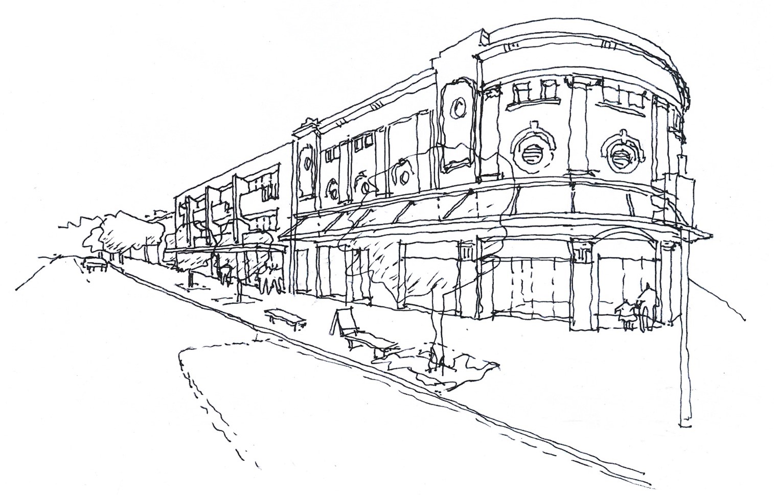 Figure E8.35: Scale of development adjoining former Regent Theatre
Development in the Local Village Centre character typology area
The existing roof parapets along Maitland Road should be maintained, with new development not detracting from these as the main building feature.
3. Roof forms do not dominate parapets, which should be the main feature of building facades in this precinct see Figure E8.36.
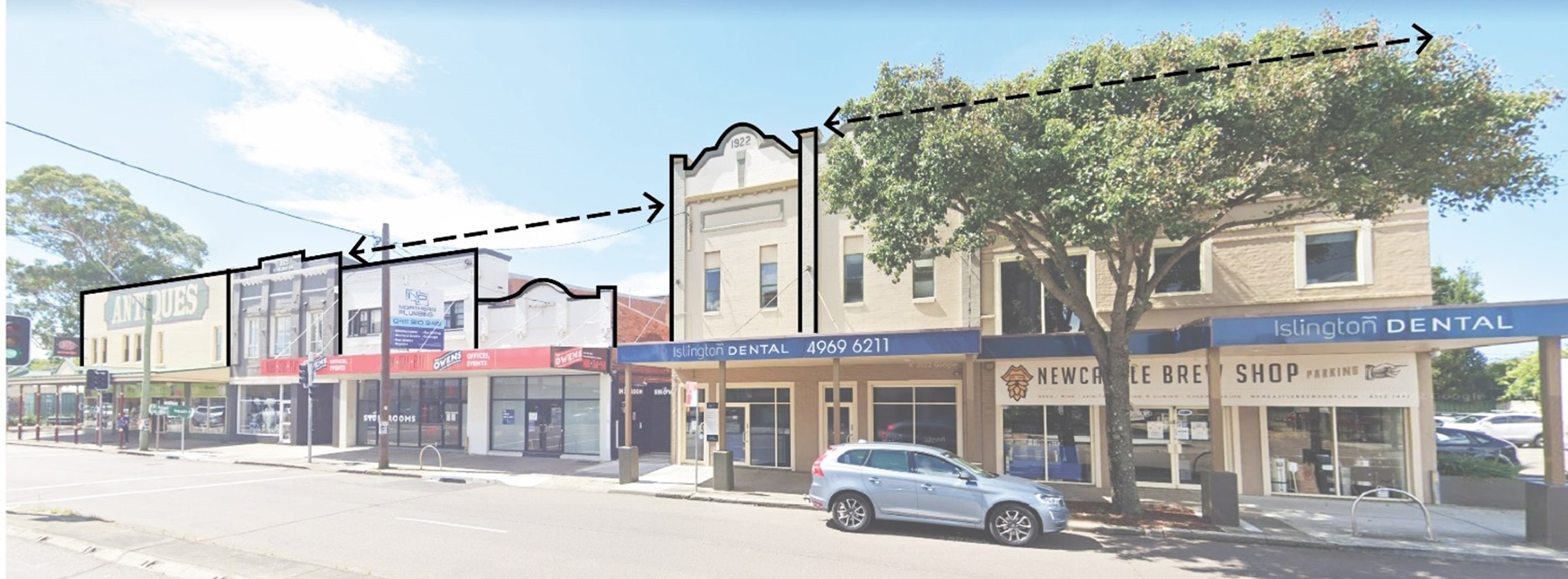 Figure E8.36: Existing parapets dominating the street edge
Development fronting Wickham Park
4. Development fronting Wickham Park should reinforce a mixed use outcome and respond to existing built form as shown in Figure E8.37.
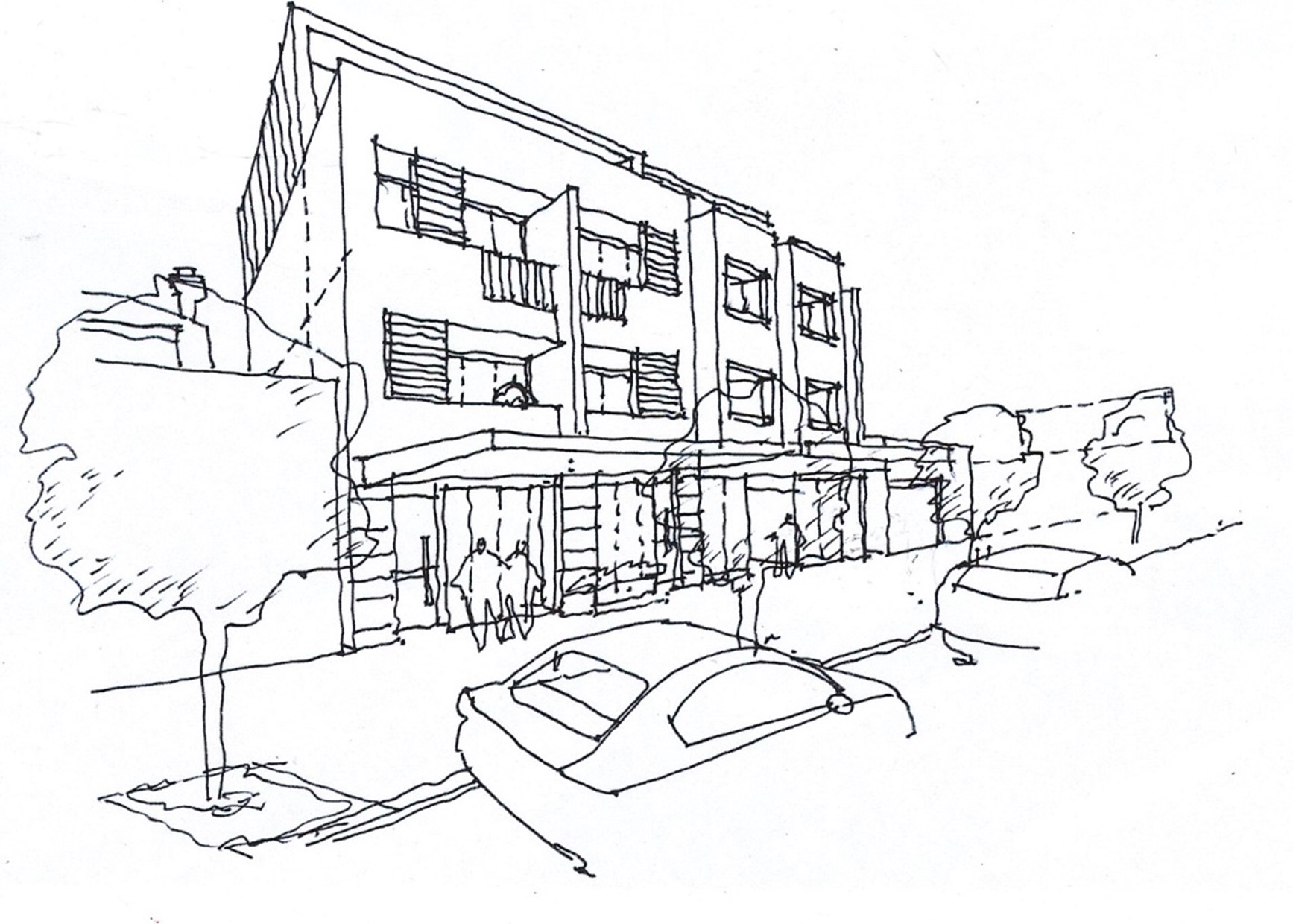 Figure E8.37: Indicative built form outcome for lots facing Wickham Park
Objectives
- Incorporate publicly accessible art into significant development to enhance the sense of place and cultural identity.
- Ensure that publicly accessible art is located in appropriate areas to optimise recognition, amenity, and safety.
- Utilise publicly accessible artworks to interpret heritage components, recognise former uses of large development sites and reflect the desired contemporary character of a place.
- Recognise and celebrate indigenous and non-indigenous cultural heritage.
- Ensure publicly accessible artwork is easy to maintain.
Controls
- Development valued over $5 million must contribute art that is publicly accessible.
- Development required to provide publicly accessible art (in accordance with control 1) must be accompanied by a public art strategy prepared by a suitable qualified person. The public art strategy is to be in accordance with any strategy/guideline that outlines CN and the Public Art Reference Group's (PARG) process and expectations. Confirmation on the provision of publicly accessible art is required from CN in conjunction with the PARG or similar committee.
- The inclusion of publicly accessible art should be considered early in the design process to enable the appropriate integration of art with the detailed fabric and form of architectural, place and landscape designs. Early consultation with CN and affiliated PARG (or similar committee) is recommended.
- Publicly accessible art should be readily visible from the street.
- Where publicly accessible art is incorporated into building facades, roof features, open spaces, walkways, building foyers, landscaping or infrastructure it should be easily recognisable as an artistic feature and labelled accordingly in a close and noticeable location.
- Publicly accessible art installations in laneways are encouraged, including creative lighting to activate the laneway at night.
- The artwork should not be climbable unless specifically designed as a play safe artwork.
- Applicants should work with a heritage consultant and/or a public artist to develop innovative ways to interpret heritage using publicly accessible art.
- Publicly accessible art should respond to the significance and character of the location and where appropriate, interpret indigenous and non-indigenous cultural heritage.
- Publicly accessible art should cover a diverse range of themes and mediums to provide visual amenity and encourage interaction.
- Publicly accessible art must be safe and durable with consideration to avoid sharp edges, protrusions at eye height, trip hazards, and prevention of vandalism and deterioration over time.
- A publicly accessible artwork maintenance plan is developed prior to the installation of each new publicly accessible artwork to ensure the effective management of artwork.
- Where art is permanent, use materials that are:
- appropriate to the landscape/environment
- resistant to vandalism
- durable and easily maintained.
| Note: Publicly accessible means the ability to be viewed or experienced from publicly accessible places. This may be within the building façade or within the front setback. Early discussions with CN staff on the design and placement of public art is encouraged. Wherever possible, publicly accessible art should be designed by local artists. The cost of publicly accessible art installations is to be 1% of the cost of construction of the development. |
These controls apply to all areas identified as Village Centre on the relevant renewal corridor map.
Character Statement
Village Centres are the focus of retail activity. These areas have the character of a traditional high street or main street, featuring active frontages and fine grain shopfronts. Village Centres are built to zero front setback with consistent awnings and respect the existing local character through adaptive reuse of heritage assets and sympathetic bulk and scale. The public domain and footpath are generally paved, providing a high standard of finish and where appropriate, features space for landscape planting and outdoor dining. Tree canopy integrates with building awnings to create a shaded footpath environment.
Objectives
- Encourage retail and commercial intensification at the ground floor within the established centres by concentrating retail and commercial activity.
- Maintain the integrity and viability of ground floor non-residential uses over time and protecting commercial floorspace from conversion to residential uses.
- Ensure ground floor uses contribute to centre activity, vibrancy, passive surveillance and local character.
- Improve and enhance the function and appearance of ground floor uses such that they are pedestrian oriented and contribute to streetscape amenity.
- Reinforce the fine grain character and continuity of ground floor shops within established centres.
- Minimise and ameliorate the effect of blank walls (with no windows or entrances) and building services at the ground level.
- Where feasible, ensure new development is accessible to all people.
Controls
- Development in a Village Centre character typology area must demonstrate consistency with the above objectives.
Building setbacks
2. Front building setbacks must be consistent with the relevant character typology setback diagram identified on the relevant corridor setback map.
3. Upper-level setbacks are encouraged to be used for open space and landscaping, provided privacy of adjoining uses are protected.
 Figure E8.38: Setback VC1 - Mid-block
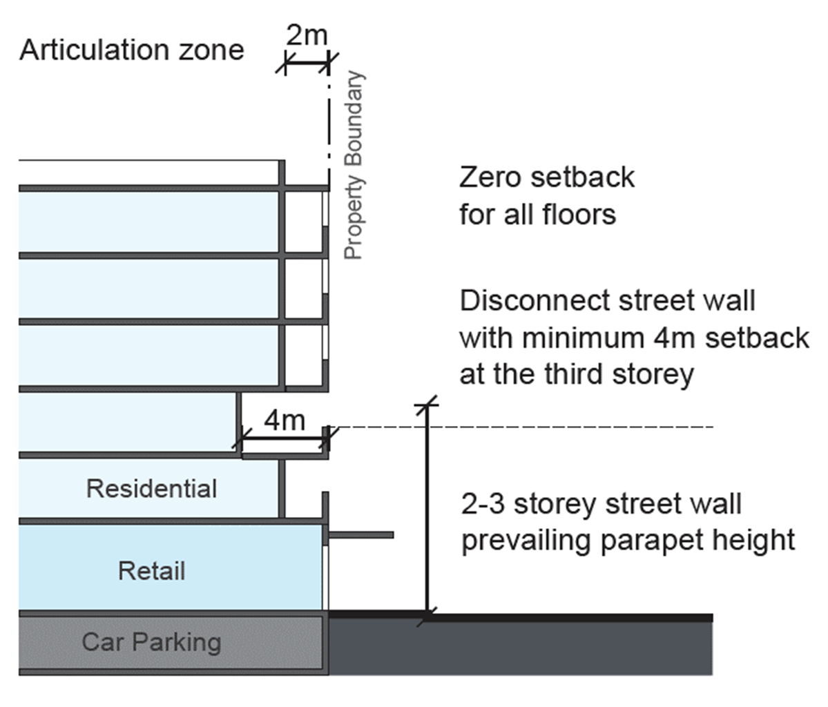 Figure E8.39: Setback VC2 – Corner block
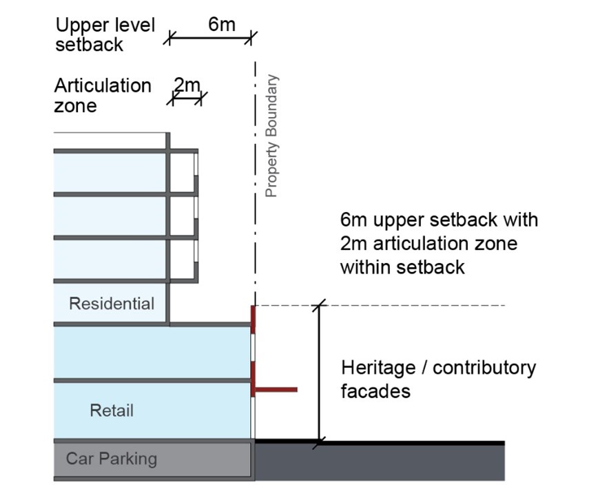 Figure E8.40: Setback VC3 - Lots with heritage/contributory facades
Active Frontage
4. A minimum 85% of street frontage identified with an VC1, VC2 or VC3 setback as are to be active uses, such as cafes, takeaway shops, retail shops, and business premises.
5. A maximum 15% of lot frontage with an LV1, LV2 or LV3 setback may be for non-active uses, such as commercial foyers or residential lobbies.
6. Car parking, services, fire doors, switchboards, and the like must be sleeved by active uses, or appropriately concealed and integrated in the design of the facade so as not to create blank or undesirable interfaces to the street.
7. On corner sites where active frontages cannot be provided to secondary streets, walls should incorporate public art, variation in building materials or other architectural or “green” wall design elements to create street interest.
Ground level floor space
8. Ground floor non-residential uses should have a minimum depth of 10m from the front property line to accommodate amenities, storage space, general back of house activities and other spatial requirements to support non-residential uses. An example is shown in Figure E8.41.
9. Residential accommodation uses are not permitted at the ground level.
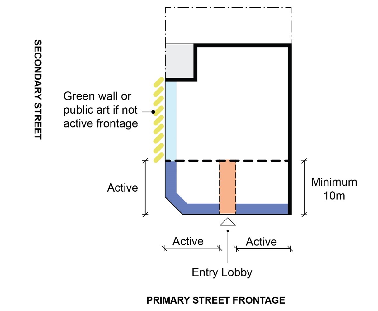 Figure E8.41: Ground level floor space and active frontages – Village Centre
Facade design
10. Ground level facades identified with an LV1, LV2 or LV3 setback should have a solid to void ratio of approximately 80% void (entries and windows) and 20% solid (walls). Openings for new development should be full height (i.e. to street level), unless a better outcome would be achieved in responding to the character of adjacent buildings.
11. Ground floor frontages identified with an LV1, LV2 or LV3 frontage width greater than 15m should be vertically articulated so as to reflect the fine grain character of the centre. Larger footprint retail shops (such as supermarkets) should be sleeved by smaller shops with individual entries to the street to maintain the fine grain.
12. The ground floor façade identified with an LV1, LV2 or LV3 setback should be built to the property line (i.e. zero setback) but may have indented entries or bays where it is consistent with existing streetscape character.
13. Facades should incorporate ‘soft edges’, such as transparent facades, large window openings, double-door entries, and spill out zones for goods on display. Consider ‘openable’ facades (windows and doors) to encourage engagement with the street and natural ventilation.
14. On corner sites ‘permeable corners’ should be considered such as splayed corner entries, glazed corners, and/or openable window or door treatments.
15. Where active frontages are predominantly glazed, up to 25% of the glazing may be frosted or semi-opaque should a level of privacy be required for the tenancy use.
16. Highly reflective finishes and use of vinyl decal signage to address blank walls or long windows is not permitted.
Entries
17. Entries for non-residential ground floor uses must be located on the primary street frontage.
18. Ground floor entries to retail, community or commercial uses are to have the same finished floor level as that of the adjacent footpath, unless required to be raised due to flood impacts.
19. Where the finished floor level is raised, universal access between the street and ground floor uses must be provided and detailed design and landscape considerations given to achieving easy access from the footpath. Level changes may also be accommodated within the building.
20. Avoid locating the length of access ramps to the primary frontage of the building. Where this is unavoidable, landscaping must be integrated to soften the street edge.
21. Vehicular parking and/or loading bays are to be accessed via a secondary street or rear lane where possible. Where secondary street or rear lane access is not available, vehicular parking and/or loading is to be at basement level or sleeved at ground level, accessed via no more than a single, two-way driveway from the primary street.
22. Where vehicular entries are located to the primary or secondary street, entry doors should be recessed a minimum of 6m.
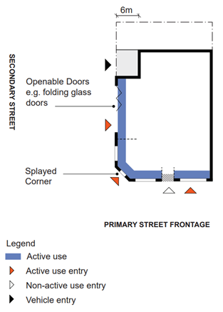 Figure E8.42: Entries and active uses – Village Centre
Blank walls
23. Large areas of blank, minimally or poorly articulated walls are not acceptable. Measures to avoid this may include windows, awnings, sun shading devices, pergolas, green walls, public art or a recognisable increased setback to the upper storey.
24. Blank walls are not permitted where facing the public domain.
25. The maximum length of any blank wall must not exceed 5m.
26. The maximum height of a blank wall must not exceed 3m.
27. Where adjacent development is unlikely to occur in the short term, blank side walls should include public art or murals, as shown Figure E8.43: Blank wall with public art in Broadmeadow.
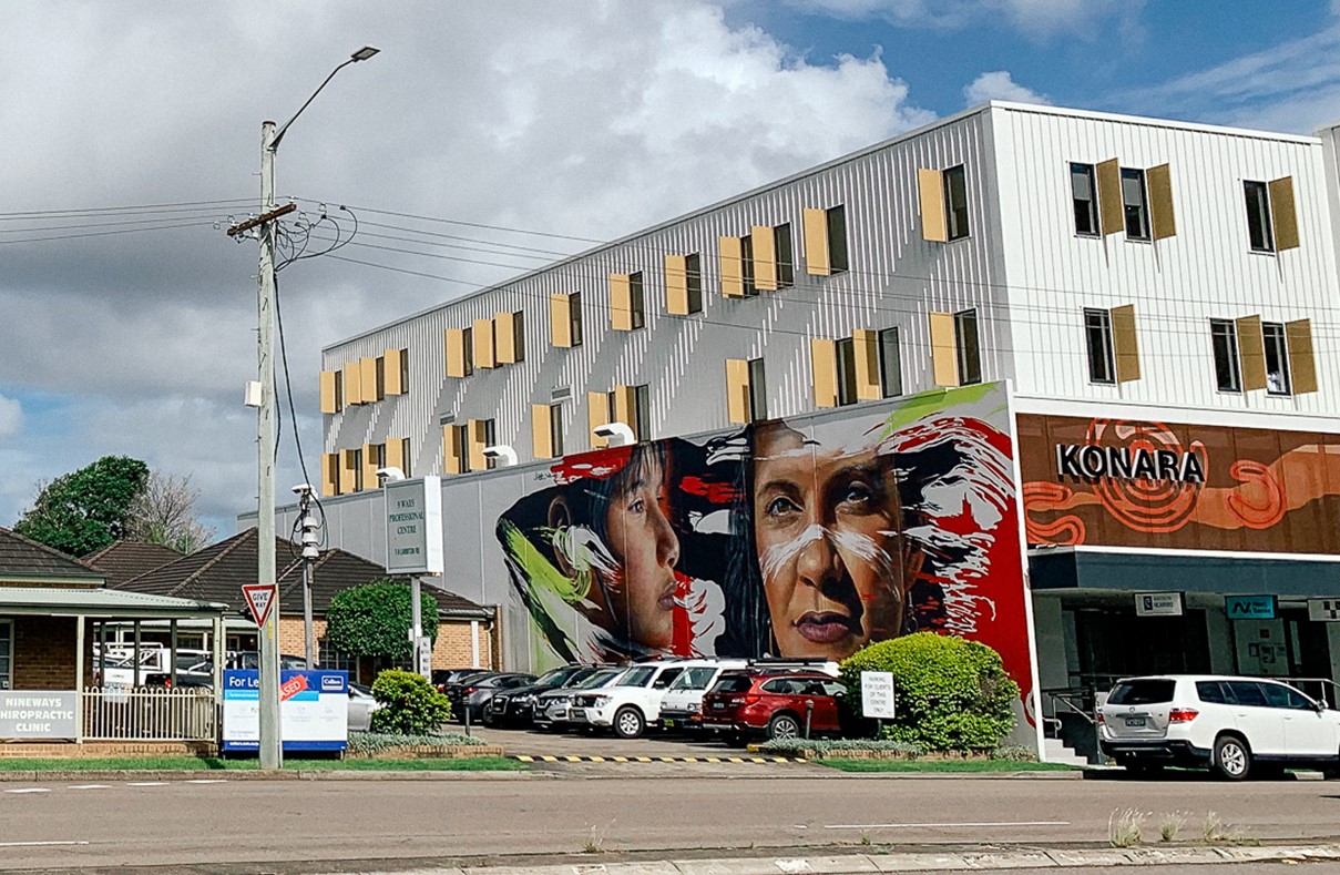 Figure E8.43: Blank wall with public art in Broadmeadow
Landscaping and deep soil
28. Non-residential development in the Village Centre character typology area has no onsite deep soil requirement and may develop to 100% site coverage.
These controls apply to all areas identified as Active-Residential on the relevant renewal corridor map.
Character Statement
Active-Residential areas cater for a variety of uses with active frontages and non-residential ground floor uses. Street corners are well defined by buildings with zero front setback, while mid-block setbacks are deeper to allow space for landscape, goods display and outdoor dining (where local amenity permits).
Mid-block setbacks assist in mediating existing uses where there may be a 6m residential setback or a car parking zone to the street.
Objectives
- Ensure the integrity and viability of non-residential ground floor uses.
- Ensure non-residential ground floor uses provide for active frontages.
- Ensure ground floor uses are pedestrian oriented and contribute to streetscape amenity, local character and passive surveillance.
- Appropriately address interfaces between non-residential and residential ground floor uses.
- Minimise and ameliorate the effect of blank walls (with no windows or entrances) and at-grade parking areas at the ground level.
- Ensure there is adequate unbuilt upon areas to allow for landscaped areas and deep soil planting capable of supporting large trees that increase urban tree canopy cover.
- Ensure that development resulting in multiple dwellings or accommodation is designed efficiently to achieve the full potential of the site, on lots that provide appropriate space for car parking, vehicle access, communal open space, deep soil planting and landscaping.
- Promote lot consolidation and ensure it does not result in isolated sites.
- Where feasible, ensure new development is accessible to all people.
Controls
- Development in an Active-Residential character typology area must demonstrate consistency with the above objectives.
Front setbacks
2. Front building setbacks must be consistent with the relevant character typology setback diagram identified on the relevant corridor setback map.
3. Upper-level setbacks are encouraged to be used for open space and landscaping, provided privacy of adjoining uses are protected.
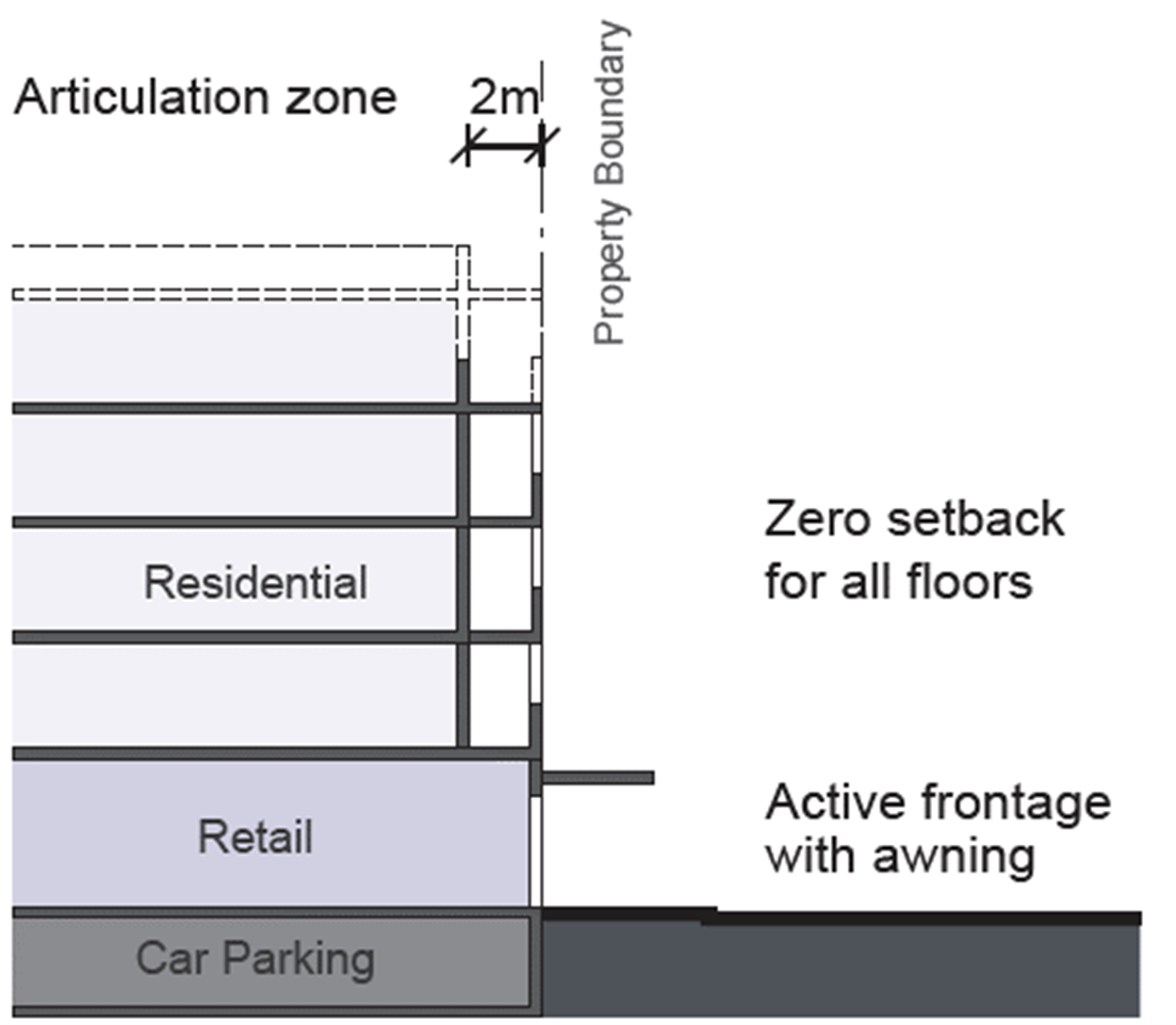 Figure E8.44: Setback AR1, 4-5 storeys – Corner sites/ general
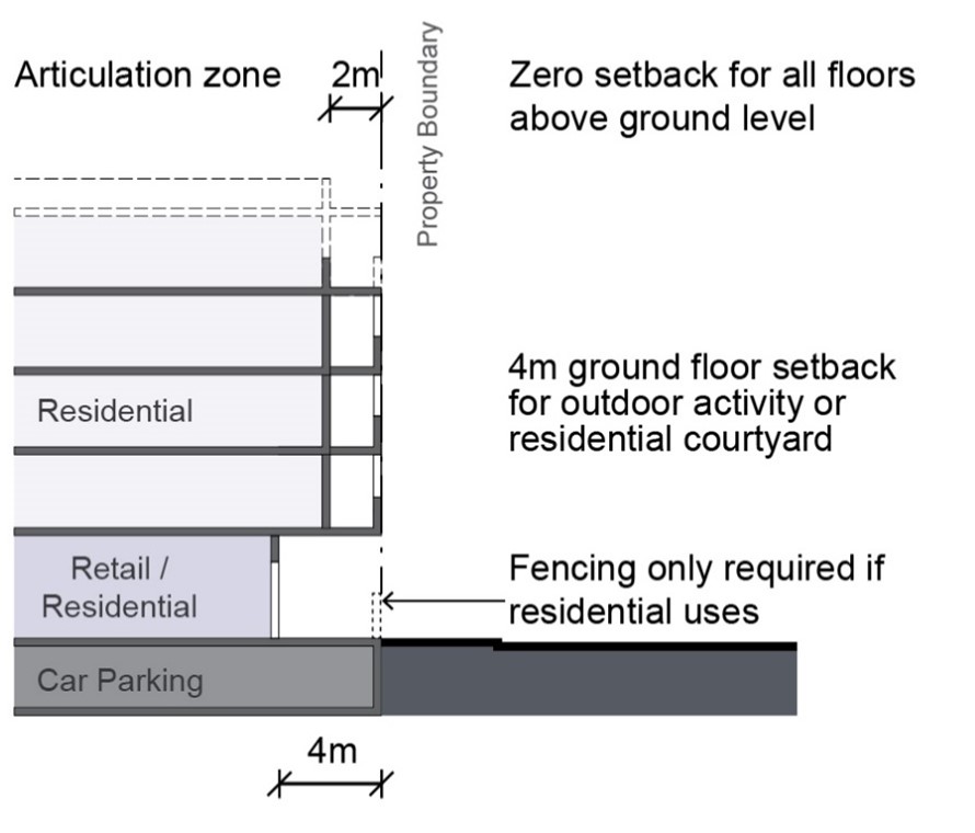 Figure E8.45: Setback AR2, 4-5 storeys – Mid-block
Rear setbacks
4. Rear setbacks are to be consistent with Table E8.2.
Table 2. Rear setbacks | |
Wall height | Rear setbacks |
Up to 4.5m | 1.5m |
4.5 - 8.5m | 3m |
Over 8.5m | 6m |
5. In the R3 Medium Density Residential, R4 High Density Residential and MU1 Mixed Use zones side or rear boundary setbacks may be reduced/built to the boundary where:
- the wall height and length match an existing or similarly constructed wall on the adjoining site; and
- the proposed wall and the wall on the adjoining property do not contain any openings; and
- the wall will not impede the flow of stormwater or overland flow paths.
6. In the R3 Medium Density Residential, R4 High Density Residential and MU1 Mixed Use zones, side and rear boundary setbacks are increased, where the site directly adjoins a site in the R2 Low Density Residential Zone.
7. Where a rear boundary adjoins a lane, development complies with C11 Development adjoining a laneway.
8. On corner lots, the boundary opposite the primary road frontage is taken to be the rear boundary for the purposes of applying setbacks.
Ground level frontages
9. For sites identified with an AR1 or AR2 setback, a minimum 85% of street frontage are to be non-residential uses, preferably active uses, such as cafes, takeaway shops, retail shops, and business premises. For corner sites, active uses are to be focused at the corner of street blocks.
10. For sites identified with an AR1 or AR2 setback, a maximum 15% of lot frontage may be for residential lobbies.
11. Car parking, services, fire doors, switchboards, and the like are to be sleeved by active uses, or appropriately concealed and integrated in the design of the façade so as not to create blank or undesirable interfaces to the street.
12. Where active frontages or non-residential uses cannot be provided to secondary streets, walls should incorporate public art, variation in building materials or other architectural or “green” wall design elements to create street interest.
Ground level floor space
13. Ground floor non-residential uses should have a minimum depth of 10m from the building line to accommodate amenities, storage space, general back of house activities and other spatial requirements to support non-residential uses.
14. Ground level floor to ceiling height must be a minimum of 4m to allow for adaptable floor plans that can support either commercial or residential uses.
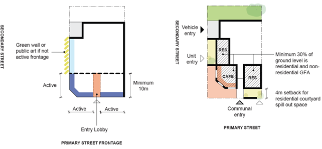 Figure E8.46: Ground level floor space and active frontages – Active-residential
Façade design
15. For sites identified with an AR1 or AR2 setback, ground level facades for non-residential uses, including residential communal areas, should have a maximum 50% solid to void ratio. Where active uses are provided, a minimum of 80% void (entries and windows) and 20% solid (walls) applies.
16. Where active frontages are predominantly glazed, up to 25% of the glazing may be frosted or semi-opaque should a level of privacy be required for the tenancy use.
17. For sites identified with an AR1 setback, the ground floor façade should be built to the property line (i.e. zero setback) but may have indented entries or bays where it is consistent with existing streetscape character.
18. Facades should incorporate ‘soft edges’, such as transparent facades, large window openings, double-door entries, and spill out zones for goods on display. Consider ‘openable’ facades (windows and doors) to encourage engagement with the street and natural ventilation.
19. Ground floor frontages greater than 15m should be vertically articulated to reflect a fine grain character.
20. Highly reflective finishes and use of vinyl decal signage to address blank walls or long windows is not permitted.
Entries
21. Where development comprises of non-residential and residential activity, separate pedestrian entrances, lift access, increased ground floor height and designated car parking must be provided.
22. Entries for non-residential ground floor uses must be located on the primary street frontage.
23. Ground floor entries to retail, commercial uses or other non-residential uses are to have the same finished floor level as that of the adjacent footpath, unless required to be raised due to flood impacts.
24. Where residential uses are located at the ground floor, ground floor units are to be provided with individual (courtyard) entries to the street to facilitate engagement with the public domain and passive surveillance.
25. Avoid locating the length of pedestrian access ramps to the primary frontage of the building. Where this is unavoidable, integrate landscaping to the street edge to create a softer edge to the street.
26. Continuous awnings must be provided to all active frontages. Breaks in awnings may be permitted for residential lobbies for legibility.
27. Vehicular parking and/or loading bays are to be accessed via a secondary street or rear lane where possible. Where secondary street or rear lane access is not unavailable, vehicular parking and/or loading is to be at basement level or sleeved at ground level, accessed via no more than a single driveway from the primary street.
28. Where vehicular entries are located to the primary or secondary street, entry doors should be recessed a minimum of 6m.
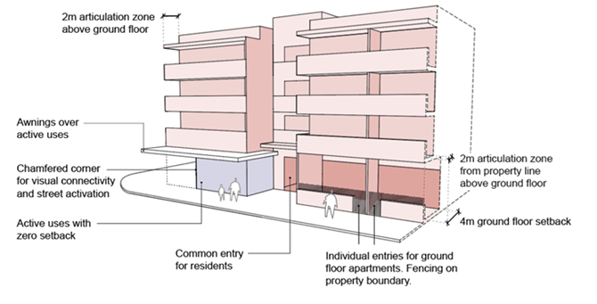 Figure E8.47: Non-residential and residential uses at ground level
Fencing
29. Fencing is only permitted for residential uses. Non-residential uses are to be built to the property boundary as per the building setback controls.
30. Ground floor residential uses may have a front fence up to 1.5m high. Solid materials, such as masonry, concrete render etc, are to be used to a maximum height of 1m high. This is to be combined with visually permeable treatments (such as slats or battens) to a height of 1.5m or landscape hedging above (any height) with or without piers to 1.5m. Colourbond must be avoided.
| Note: Strip footing on fencing should be avoided where deep soil is proposed or there are existing trees. |
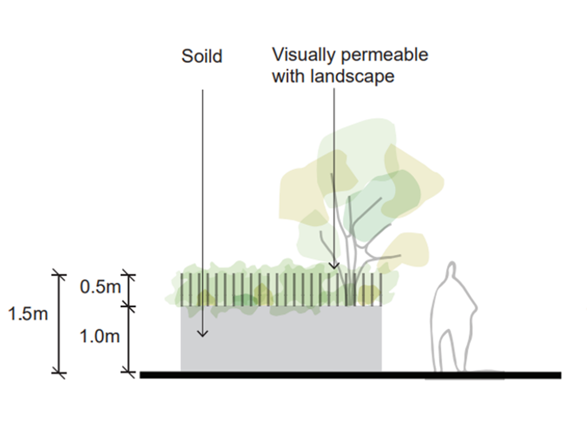 Figure E8.48: Active-residential fencing controls
Minimum lot size and frontage
31. For the development types listed in Table E8.03 and frontage width must be equal to or greater than the minimums specified in Table E8.03.
Table E8.03: Minimum lot and frontage size | ||
Development type | Minimum lot size | Minimum frontage width |
Boarding houses Hostels Multi dwelling housing Residential flat buildings Shop top housing | 1,000m2 | 18m |
32. Development for the purpose of residential flat buildings, multi dwelling housing or shop top housing is not to result in the creation of an isolated site that could have been developed in compliance with the relevant planning controls. Appropriate documentary evidence to demonstrate that a genuine and reasonable attempt has been made to purchase an isolated site based on a fair market value.
33. Where amalgamation of the isolated site is not feasible, applicants will be required to demonstrate that an orderly and economic use and development of the separate sites can be achieved.
34. The development of existing isolated sites is not to detract from the character of the streetscape and is to achieve a satisfactory level of amenity including solar access, visual and acoustic privacy. Development of existing isolated sites may not achieve the maximum potential, particularly height and floor space ratio, and will be assessed on merit.
35. Where adjacent sites are developing concurrently, site planning options for development as an amalgamated site are to be explored.
Blank walls
36. Large areas of blank, minimally or poorly articulated walls are not acceptable. Measures to avoid this may include windows, awnings, sun shading devices, pergolas, green walls, public art or a recognisable increased setback to the upper storey.
37. Blank walls are not permitted where facing the public domain.
38. The maximum length of any blank wall must not exceed 5m.
39. The maximum height of a blank wall must not exceed 3m.
40. Where adjacent development is unlikely to occur in the short term, blank side walls should include public art or murals, as shown in Figure E8.49.
 Figure E8.49: Blank wall with public art in Broadmeadow
Landscaping and deep soil
41. Non-residential development should provide deep soil planting at side setback with a minimum width and length of 2m.
42. The minimum landscaped area that must be provided on a lot is shown in Table E8.04.
Table E8.04: Minimum landscaped area. | ||
Lot Area | Minimum landscaped area | Minimum deep soil zone |
<600m2 | 25% of site area | 12% |
>600m2 | 30% of site area | 15% |
| Note: New and existing trees must be clearly indicated in landscape plans. |
43. Deep soil planting must have a minimum width and length of 2m.
- Deep soil planting must have a minimum width and length of 2m.
- Deep soil planting must have a minimum width and length of 2m.
These controls apply to all areas identified as Apartments on the relevant renewal corridor map.
Character Statement
The Apartments typology reinforces and supports the characteristics of medium to high density neighbourhoods. Residential flat buildings and apartments are built with ground floor residential uses and a 6m landscaped setback. Setbacks may be reduced on corner sites.
Fencing is a consistent size and uses common materials across the corridors, providing space for landscape planting to soften building edges and improve tree canopy cover.
Ground floor apartments address the primary street frontage with individual dwelling entries while vehicular and waste access priorities the uses of rear lanes or secondary streets. Existing road and footpath levels are respected and maintained, where possible avoiding ground floor levels lower than the street.
Objectives
- Ensure consistent definition of the street edge via setbacks, fencing and landscaping.
- Appropriately balance noise attenuation and visual privacy requirements with engagement with the public domain.
- Increase opportunities for landscaping and deep soil planting in the front setback, facing the public domain.
- Ensure there is adequate unbuilt upon areas to allow for landscaped areas and deep soil planting capable of supporting large trees that increase urban tree canopy cover.
- Ensure that development resulting in multiple dwellings or accommodation is designed efficiently to achieve the full potential of the site, on lots that provide appropriate space for car parking, vehicle access, communal open space, deep soil planting and landscaping.
- Promote lot consolidation and ensure it does not result in isolated sites.
- Where feasible, ensure new development is accessible to all people.
Controls
- Development in an Apartments character typology area must demonstrate consistency with the above objectives.
Front setback
2. Front building setbacks must be consistent with the relevant character typology setback diagram identified on the relevant corridor setback map.
3. Upper-level setbacks are encouraged to be used for open space and landscaping, provided privacy of adjoining uses are protected.
4. Front setbacks are to provide landscaping and deep soil to support large trees.
 Figure E8.50: Residential setback
 Figure E8.51: Front prevailing setback and articulation zone
Read setbacks
5. Rear setbacks are to be consistent with Table E8.05.
Table E8.05. Rear setbacks | |
Wall height | Rear setbacks |
Up to 4.5m | 1.5m |
4.5 - 8.5m | 3m |
Over 8.5m | 6m |
6. In the R3 Medium Density Residential, R4 High Density Residential and MU1 Mixed Use zones side or rear boundary setbacks may be reduced/built to the boundary where:
- the wall height and length match an existing or similarly constructed wall on the adjoining site; and
- the proposed wall and the wall on the adjoining property do not contain any openings; and
- the wall will not impede the flow of stormwater or overland flow paths.
7. In the R3 Medium Density Residential, R4 High Density Residential and MU1 Mixed Use zones, side and rear boundary setbacks are increased, where the site directly adjoins a site in the R2 Low Density Residential Zone.
8. Where a rear boundary adjoins a lane, development complies with C11 Development adjoining a laneway.
9. On corner lots, the boundary opposite the primary road frontage is taken to be the rear boundary for the purposes of applying setbacks.
Ground level floor space
10. A minimum 30% of the ground floor of the building must be occupied by residential GFA to ensure the ground level is not wholly occupied by car parking, building services and communal amenities. This is to ensure ground flood activation and screen ground floor car parking from the public domain. Residential GFA must be located to the primary street.
11. Ground floor residential GFA should result in at least two residential units.
12. Ground floor residential GFA may include communal facilities such as shared workspaces.
 Figure E8.52: Ground level floor space – Apartments
Facade design
13. Car parking, services, fire doors, switchboards, and the like are to be appropriately concealed and integrated in the design of the facade so as not to create blank or undesirable interfaces to the street.
Residential entries
14. Ground floor units are to be provided with individual (courtyard) entries to the street to facilitate engagement with the public domain and passive surveillance. These entries should look and feel materially different to a communal building entry.
15. Residential entries must not be located below street or footpath level.
16. Residential uses at ground floor should be designed so that the ground floor is raised above the finished footpath level to provide for occupant privacy, up to a maximum of 1.2m.
17. Where the finished floor level is raised, universal access between the street and ground floor uses must be provided and detailed design and landscape considerations given to achieving easy access from the footpath. Level changes may also be accommodated within the building.
18. The length of access ramps should not be located along the primary frontage of the building. Where this is unavoidable, landscaping must be integrated to the street edge to create a softer edge to the street.
19. Vehicular parking must be accessed via a secondary street or rear lane where possible. Where secondary street or rear lane access is not unavailable, vehicular parking and/or loading is to be at basement level or sleeved by units at ground level, accessed via no more than a single driveway from the primary street.
-ground-level-entries.png&hash=a89028a14a87434fdfcc8763f9f147ed6220628443ef51b58eb6c5960dbd50e1) Figure E8.53: (Right) Ground level entries – apartments
Figure E8.53: (Right) Ground level entries – apartmentsFencing
20. Ground floor residential uses must have a front fence up to 1.5m high. Solid materials, such as masonry, concrete render etc, are to be used to a maximum height of 1m high. This is to be combined with visually permeable treatments (such as slats or battens) to a height of 1.5m or landscape hedging above (any height) with or without piers to 1.5m. Colourbond must be avoided.
-residential-fencing-controls.png&hash=e91f4d3c5ddb39ea4c5ea99735a0aea5f1d0b2ad9b6d3143184912a8553c3d09) Figure E8.54: (Right) residential fencing controls
Figure E8.54: (Right) residential fencing controls
Minimum lot size and frontage
21. For the development types listed in Table E8.06, lot size and frontage width must be equal to or greater than the minimums specified in Table E8.06.
Table E8.06: Minimum lot and frontage size | ||
Development type | Minimum lot size | Minimum frontage width |
Boarding houses Hostels Multi dwelling housing Residential flat buildings Shop top housing | 1,000m2 | 18m |
22. Development for the purpose of residential flat buildings, multi dwelling housing or shop top housing is not to result in the creation of an isolated site that could have been developed in compliance with the relevant planning controls. Council will require appropriate documentary evidence to demonstrate that a genuine and reasonable attempt has been made to purchase an isolated site based on a fair market value.
23. Where amalgamation of the isolated site is not feasible, applicants will be required to demonstrate that an orderly and economic use and development of the separate sites can be achieved.
24. The development of existing isolated sites is not to detract from the character of the streetscape and is to achieve a satisfactory level of amenity including solar access, visual and acoustic privacy. Development of existing isolated sites may not achieve the maximum potential, particularly height and floor space ratio, and will be assessed on merit.
25. Where adjacent sites are developing concurrently, site planning options for development as an amalgamated site are to be explored.
Blank walls
26. Large areas of blank, minimally or poorly articulated walls are not acceptable. Measures to avoid this may include windows, awnings, sun shading devices, pergolas, green walls, public art or a recognisable increased setback to the upper storey.
27. Blank walls are not permitted where facing the public domain.
28. The maximum length of any blank wall must not exceed 5m.
29. The maximum height of a blank wall must not exceed 3m.
30. Where adjacent development is unlikely to occur in the short term, blank side walls should include public art or murals, as shown in Figure E8.55:
 Figure E8.55: Blank wall with public art in Broadmeadow
Landscaping and deep soil
31. Non-residential development should provide deep soil planting at front setback or side setback with a minimum width and length of 2m.
32. The minimum landscaped area that must be provided on a lot is shown in Table E8.07.
Table E8.07: Minimum landscaped area | ||
Lot Area | Minimum landscaped area | Minimum deep soil zone |
<600m2 | 25% of site area | 12% |
>600m2 | 30% of site area | 15% |
| Note: New and existing trees must be clearly indicated in landscape plans. |
33. Deep soil planting must have a minimum width and length of 2m.
These controls apply to all areas identified as Auto-Business on the relevant renewal corridor map.
Character statement
The ‘Auto-Business’ Character Typology applies to areas generally zoned MU1 Mixed Use, R4 High Density, or E1 Local Centre but that are currently occupied by vehicle-oriented businesses such as car yards, petrol stations, vehicle repair shops and the like, which are unlikely to change in the near future. To help concentrate residential development activity in other areas of the corridors and minimise land use conflict, the current uses and building typologies in these areas should be allowed to continue until significant changes in local character or transport infrastructure dictate a need for these areas to transition to other uses. Development in these areas should respond to existing rather than future character, while providing opportunities for adaptive reuse of buildings and access arrangements that permit easy conversion to future alternative uses. Development in these areas should seek to significantly increase deep soil planting and landscaping to help mitigate the impacts of urban heat and improve the public realm.
Objectives
- Ensure the integrity and viability of non-residential ground floor uses.
- Ensure non-residential ground floor uses provide for active frontages.
- Ensure ground floor uses are pedestrian oriented and contribute to streetscape amenity, local character and passive surveillance.
- Appropriately address interfaces between existing non-residential development and future mixed use development.
- Minimise and ameliorate the effect of blank walls (with no windows or entrances) and at-grade parking areas at the ground level.
- Ensure that development resulting in multiple dwellings or accommodation is designed efficiently to achieve the full potential of the site, on lots that provide appropriate space for car parking, vehicle access, communal open space, deep soil planting and landscaping.
- Promote lot consolidation and ensure it does not result in isolated sites.
- Where feasible, ensure new development is accessible to all people.
Controls
- Development in an Auto-Business character typology area must demonstrate consistency with the above objectives.
Front setback
2. Front building setbacks must be consistent with the relevant character typology setback diagram identified on the relevant corridor setback map.
3. Front setbacks are to generally be 6m.
4. Front setbacks may be altered to an alternative character typology setback where:
- the setback matches an existing or similarly constructed wall on the adjoining site, and
- the setback is consistent with the Auto-Business character statement and results in a more appropriate built form outcome; and
- the minimum landscaping and deep soil provision can still be achieved.
 Figure E8.56: Front prevailing setback and articulation zone
Read setbacks
5. Rear setbacks are to be consistent with Table E8.08.
Table E8.08: Rear setbacks | |
Wall height | Rear setbacks |
Up to 4.5m | 1.5m |
4.5 - 8.5m | 3m |
Over 8.5m | 6m |
6. In the R3 Medium Density Residential, R4 High Density Residential and MU1 Mixed Use zones side or rear boundary setbacks may be reduced/built to the boundary where:
- the wall height and length match an existing or similarly constructed wall on the adjoining site; and
- the proposed wall and the wall on the adjoining property do not contain any openings; and
- the wall will not impede the flow of stormwater or overland flow paths.
7. In the R3 Medium Density Residential, R4 High Density Residential and MU1 Mixed Use zones, side and rear boundary setbacks are increased, where the site directly adjoins a site in the R2 Low Density Residential Zone.
8. Where a rear boundary adjoins a lane, development complies with Section C11 Development adjoining a laneway.
9. On corner lots, the boundary opposite the primary road frontage is taken to be the rear boundary for the purposes of applying setbacks.
Ground level frontage
10. For sites with a frontage of 40m or greater, a minimum 50% of the frontage must be built to the property boundary.
11. Minimum 85% of frontage built to the boundary should provide for active uses, such as cafes, takeaway shops, retail shops, and business premises. Where a combination of non-residential and active uses are provided, active uses should be focused at the corners of buildings.
12. Car parking, services, fire doors, switchboards, and the like are to be sleeved by active uses, or appropriately concealed and integrated in the design of the façade so as not to create blank or undesirable interfaces to the street.
13. On corner site where active frontages cannot be provided to secondary streets, walls should incorporate public art, variation in building materials or other architectural or “green” wall design elements to create street interest.
Ground level floor space
14. A minimum 50% of the ground floor of the building must be occupied by non-residential GFA. This is to ensure ground flood activation and screen ground floor car parking from the public domain.
15. Ground floor non-residential uses should have a minimum depth of 10m from the building line to accommodate amenities, storage space, general back of house activities and other spatial requirements to support non-residential uses.
16. Floor to floor height must be a minimum of 4m to allow for adaptable floor plans that can support either commercial or residential uses in future.
17. Habitable residential accommodation uses are not permitted at the ground level. This control does not apply in the Adamstown renewal corridor.
 Figure E8.57: Ground level floorspace – Auto-business
Facade design
18. Ground level facades for non-residential uses should have a maximum 50% solid to void ratio. Where active uses are provided, a minimum of 80% void (entries and windows) and 20% solid (walls) applies.
19. Where active frontages are predominantly glazed, up to 25% of the glazing may be frosted or semi-opaque should a level of privacy be required for the tenancy use.
20. Facades at the property boundary should incorporate ‘soft edges’, such as transparent facades, large window openings, double-door entries, and spill out zones for goods on display. Consider ‘openable’ facades (windows and doors) to encourage engagement with the street and natural ventilation.
21. Ground floor frontages greater than 15m should be vertically articulated with recesses generally spaced at 10m-20m intervals, or in response to the existing character of the street.
22. Highly reflective finishes and use of vinyl decal signage to address blank walls or long windows is not permitted.
Entries
23. Where development comprises of non-residential and residential activity, separate pedestrian entrances, lift access, increased ground floor height and designated car parking must be provided.
24. Entries for non-residential ground floor uses must be located on the primary street frontage.
25. Ground floor entries to retail, commercial uses or other non-residential uses are to have the same finished floor level as that of the adjacent footpath, unless required to be raised due to flood impacts.
26. Where the finished floor level is raised, universal access between the street and ground floor uses must be provided and detailed design and landscape considerations given to achieving easy access from the footpath. Level changes may also be accommodated within the building.
27. Avoid locating the length of pedestrian access ramps to the primary frontage of the building. Where this is unavoidable, integrate landscaping to the street edge to create a softer edge to the street.
28. Continuous awnings must be provided to all active frontages if built to property boundary. Breaks in awnings may be permitted for residential lobbies for legibility.
29. Vehicular parking and/or loading bays are to be accessed via a secondary street or rear lane where possible. Where secondary street or rear lane access is not unavailable, vehicular parking and/or loading is to be at basement level or sleeved at ground level, accessed via no more than a single driveway from the primary street.
30. Where vehicular entries are located to the primary or secondary street, entry doors should be recessed a minimum of 6m.
Fencing
31. Fencing is permitted for non-residential uses where it is required for security purposes. Black palisade fencing up to 1.8m should be used, combined with landscaping and tree planting where appropriate.
 Figure E8.58: Non-residential fencing controls
Minimum lot size and frontage
32. For the development types listed in Table E8.09, lot size and frontage width must be equal to or greater than the minimums specified in Table E8.09.
Table E8.09: Minimum lot and frontage size | ||
Development type | Minimum lot size | Minimum frontage width |
Boarding houses Hostels Multi dwelling housing Residential flat buildings Shop top housing | 1,000m2 | 18m |
33. Development for the purpose of residential flat buildings, multi dwelling housing or shop top housing is not to result in the creation of an isolated site that could have been developed in compliance with the relevant planning controls. Council will require appropriate documentary evidence to demonstrate that a genuine and reasonable attempt has been made to purchase an isolated site based on a fair market value.
34. Where amalgamation of the isolated site is not feasible, applicants will be required to demonstrate that an orderly and economic use and development of the separate sites can be achieved.
35. The development of existing isolated sites is not to detract from the character of the streetscape and is to achieve a satisfactory level of amenity including solar access, visual and acoustic privacy. Development of existing isolated sites may not achieve the maximum potential, particularly height and floor space ratio, and will be assessed on merit.
36. Where adjacent sites are developing concurrently, site planning options for development as an amalgamated site are to be explored.
Blank walls
37. Large areas of blank, minimally or poorly articulated walls are not acceptable. Measures to avoid this may include windows, awnings, sun shading devices, pergolas, green walls, public art or a recognisable increased setback to the upper storey.
38. Blank walls are not permitted where facing the public domain.
39. The maximum length of any blank wall must not exceed 5m.
40. The maximum height of a blank wall must not exceed 3m.
41. Where adjacent development is unlikely to occur in the short term, blank side walls should include public art or murals, as shown in Figure E8.59.
 Figure E8.59: Blank wall with public art in Broadmeadow
Landscaping and deep soil
42. Non-residential development should provide deep soil planting at front setback or side setback with a minimum width and length of 2m.
43. The minimum landscaped area that must be provided on a lot is shown in Table E8.10.
Table E8.10: Minimum landscaped area | ||
Lot Area | Minimum landscaped area | Minimum deep soil zone |
<600m2 | 25% of site area | 12% |
>600m2 | 30% of site area | 15% |
| Note: New and existing trees must be clearly indicated in landscape plans. |
44. Deep soil planting must have a minimum width and length of 2m.
These controls apply to all areas identified as Transition-Residential on the relevant renewal corridor map.
Character statement
The ‘Transition-Residential’ Character Typology applies to areas where the surrounding character is primarily residential, but businesses premises operate along main road corridors in a range of building typologies. The future character of these areas is a transition between the ‘Active-Residential’ and ‘Apartments’ character typologies, reflecting how the current built form has been slow to respond to the underlying planning controls.
Objectives
- Establish a primarily residential interface at the ground level.
- Appropriately address interfaces between existing non-residential development and future residential development.
- Ensure consistent definition of the street edge via setbacks, fencing and landscaping.
- Appropriately balance noise attenuation and visual privacy requirements with engagement with the public domain.
- Provide opportunities for landscaping and deep soil planting at the street interface.
- Ensure that development resulting in multiple dwellings or accommodation is designed efficiently to achieve the full potential of the site, on lots that provide appropriate space for car parking, vehicle access, communal open space, deep soil planting and landscaping.
- Promote lot consolidation and ensure it does not result in isolated sites.
- Where feasible, ensure new development is accessible to all people.
Controls
- Development in a Transition-residential character typology area must demonstrate consistency with the above objectives.
Front setback
2. Front building setbacks must be consistent with the relevant character typology setback diagram identified on the corridor setback map.
3. Front setbacks may be altered to an alternative character typology setback where:
- the setback matches an existing or similarly constructed wall on the adjoining site; and
- the setback is consistent with the character statement and results in a more appropriate built form outcome; and
- the minimum landscaping and deep soil provision can still be achieved.
 Figure E8.60: Setback transition - residential
 Figure E8.61: Front prevailing setback and articulation zone
Read setbacks
4. Rear setbacks are to be consistent with Table E8.11.
Table E8.11: Rear setbacks | |
Wall height | Rear setbacks |
Up to 4.5m | 1.5m |
4.5 - 8.5m | 3m |
Over 8.5m | 6m |
5. In the R3 Medium Density Residential, R4 High Density Residential and MU1 Mixed Use zones side or rear boundary setbacks may be reduced/built to the boundary where:
- the wall height and length match an existing or similarly constructed wall on the adjoining site; and
- the proposed wall and the wall on the adjoining property do not contain any openings; and
- the wall will not impede the flow of stormwater or overland flow paths.
6. In the R3 Medium Density Residential, R4 High Density Residential and MU1 Mixed Use zones, side and rear boundary setbacks are increased, where the site directly adjoins a site in the R2 Low Density Residential zone.
7. Where a rear boundary adjoins a lane, development complies with C11 Development adjoining a laneway.
8. On corner lots, the boundary opposite the primary road frontage is taken to be the rear boundary for the purposes of applying setbacks.
Ground level floor space
9. A minimum 30% of the ground floor of the building must be occupied by residential and/or non-residential GFA to ensure the ground level is not wholly occupied by car parking, building services and communal amenities. This is to ensure ground flood activation and screen ground floor car parking from the public domain. Residential GFA must be located to the primary street.
10. Where non-residential uses are provided at ground level, active uses such as cafes, takeaway shops, retail shops, and business premises are preferred.
 Figure E8.62: Ground level floor space transition-residential
Facade design
11. Car parking, services, fire doors, switchboards, and the like are to be appropriately concealed and integrated in the design of the façade so as not to create blank or undesirable interfaces to the street.
12. Where active uses are provided, a minimum of 80% void (entries and windows) and 20% solid (walls) applies.
13. Where active frontages are predominantly glazed, up to 25% of the glazing may be frosted or semi-opaque should a level of privacy be required for the tenancy use.
Entries
14. Ground floor units are to be provided with individual (courtyard) entries to the street to facilitate engagement with the public domain and passive surveillance.
15. Residential entries must not be located below street or footpath level.
16. Residential uses at ground floor should be designed so that the ground floor is raised above the finished footpath level to provide for occupant privacy, up to a maximum of 1.2m.
17. Where the finished floor level is raised, universal access between the street and ground floor uses must be provided and detailed design and landscape considerations given to achieving easy access from the footpath. Level changes may also be accommodated within the building.
18. The length of access ramps should not be located along the primary frontage of the building. Where this is unavoidable, landscaping must be integrated to the street edge to create a softer edge to the street.
19. Vehicular parking should be accessed via a secondary street or rear lane where possible. Where secondary street or rear lane access is not unavailable, vehicular parking and/or loading is to be at basement level or sleeved by units at ground level, accessed via no more than a single driveway from the primary street.
20. Where vehicular entries are located to the primary or secondary street, entry doors should be recessed a minimum of 6m.
 Figure E8.63: Ground level entries transition-residential
 Figure E8.64: Non-residential and residential uses at ground level
Fencing
21. Ground floor residential uses must have a front fence up to 1.5m high. Solid materials, such as masonry, concrete render etc, are to be used to a maximum height of 1m high. This is to be combined with visually permeable treatments (such as slats or battens) to a height of 1.5m or landscape hedging above (any height) with or without piers to 1.5m. Colourbond must be avoided.
 Figure E8.65: Fencing controls
Minimum lot size and frontage
22. For the development types listed in Table E8.12, lot size and frontage width must be equal to or greater than the minimums specified in Table E8.12.
Table E8.12: Minimum lot and frontage size | ||
Development type | Minimum lot size | Minimum frontage width |
Boarding houses Hostels Multi dwelling housing Residential flat buildings Shop top housing | 1,000m2 | 18m |
23. Development for the purpose of residential flat buildings, multi dwelling housing or shop top housing is not to result in the creation of an isolated site that could have been developed in compliance with the relevant planning controls. Council will require appropriate documentary evidence to demonstrate that a genuine and reasonable attempt has been made to purchase an isolated site based on a fair market value.
24. Where amalgamation of the isolated site is not feasible, applicants will be required to demonstrate that an orderly and economic use and development of the separate sites can be achieved.
25. The development of existing isolated sites is not to detract from the character of the streetscape and is to achieve a satisfactory level of amenity including solar access, visual and acoustic privacy. Development of existing isolated sites may not achieve the maximum potential, particularly height and floor space ratio, and will be assessed on merit.
26. Where adjacent sites are developing concurrently, site planning options for development as an amalgamated site are to be explored.
Blank walls
27. Large areas of blank, minimally or poorly articulated walls are not acceptable. Measures to avoid this may include windows, awnings, sun shading devices, pergolas, green walls, public art or a recognisable increased setback to the upper storey.
28. Blank walls are not permitted where facing the public domain.
29. The maximum length of any blank wall must not exceed 5m.
30. The maximum height of a blank wall must not exceed 3m.
31. Where adjacent development is unlikely to occur in the short term, blank side walls should include public art or murals, as shown Figure E8.66.
 Figure E8.66: Blank wall with public art in Broadmeadow
Landscaping and deep soil
32. Non-residential development should provide deep soil planting at front setback or side setback with a minimum width and length of 2m.
33. The minimum landscaped area that must be provided on a lot is shown in the following Table E8.13.
Table E8.13: Minimum landscaped area | ||
Lot area | Minimum landscaped area | Minimum deep soil zone |
<600m2 | 25% of site area | 12% |
>600m2 | 30% of site area | 15% |
| Note: New and existing trees must be clearly indicated in landscape plans. |
34. Deep soil planting must have a minimum width and length of 2m.